

Purpose of EWP Insulation Resistance (IR) Testing
IR Testing confirms the surface condition and insulation integrity of insulated boom inserts between scheduled electrical tests required by AS/NZS 1418.10.
Because insulation can be affected by rain, moisture, fog, or contamination, this practice includes:
Visual inspection
Cleaning and polishing booms
Insulation resistance measurement of each boom section
Operators shall complete IR testing on Work Group Meeting days or whenever an EWP returns from a major service.
This confirms the EWP chassis and boom inserts remain safe and effective.
Note: Testing is not required if a scheduled electrical test will occur within two weeks of the Work Group Meeting or major service.

Complete the EWP Daily Checklist
Prepare the EWP for test in a location away from traffic and pedestrians.
M

Wipe down any contaminants off the insulated sections of the EWP boom with Polywater Boom wipes

Clean the sections of boom between the "Chassis Insulator" markings

Including the Fly Jib between the 'Boom Insulator' makings

Check and confirm all the dirt and grime has been removed

Use a 5kV Insulation Resistance Tester with clamp leads. Test leads with banana plugs may be required for EWPs fitted with Megger Test Points.

Before starting, confirm the calibration date information is correct
Test the 'Open Circuit' functionality of the Insulation Resistance Tester
Plug the leads in, making sure they are not contacting any metal components or each other.
Select the 5kV function of the tester and press and hold the test button.
A correct 'Open Circuit' test result should be greater than 100GΩ
Test the 'Closed Circuit' functionality of the Insulation Resistance Tester
Plug the leads in, making sure they are connected.
Select the 5kV function of the tester and press and hold the test button.
A correct test result should be as close to zero as possible.

Remove the EWP boom tie-down straps and elevate the upper and lower booms, making sure both booms and the basket are clear of their respective rests.

Make sure all the booms and basket are a minimum 100mm clear


Before commencing IR testing, connect the insulation resistance tester to the Earth Stud of the EWP

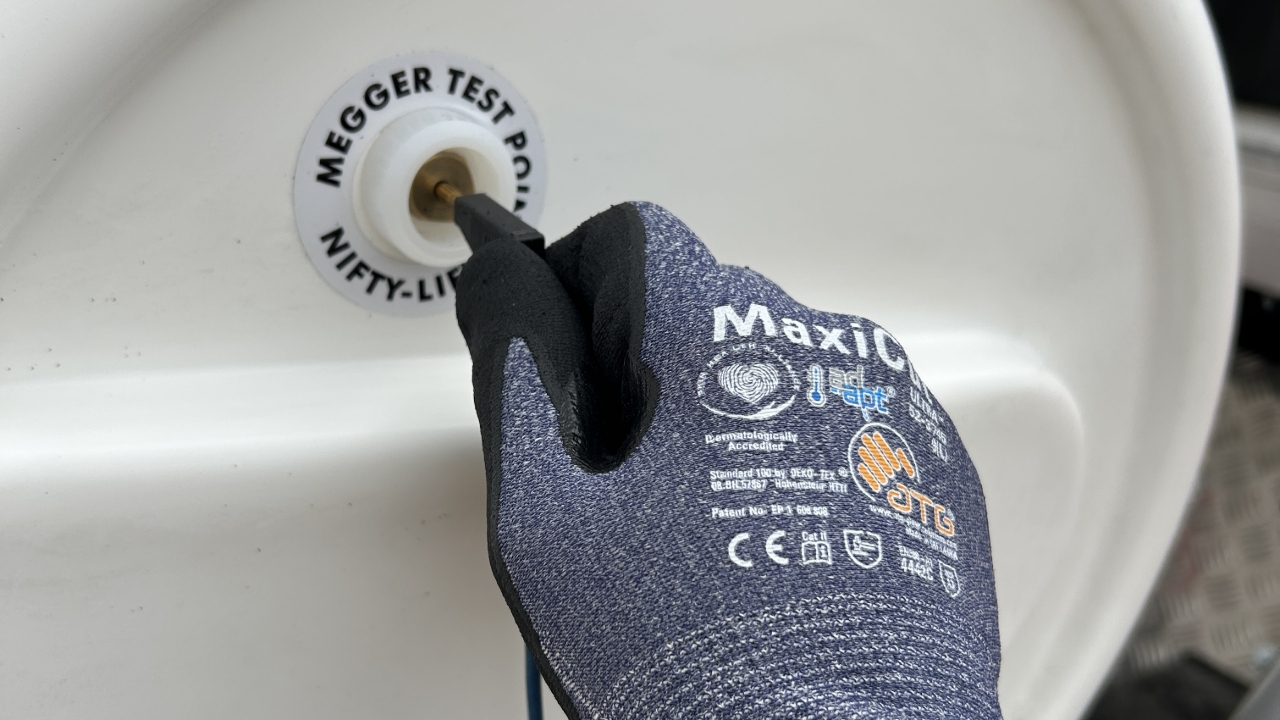
Some Fly Jibs may have 'Megger Test Point' positions fitted either side of the 'Insulated Boom'.
Insert the test leads into both test points.

Then connect the Insulation Resistance Tester clamps to the fitted leads


Plug the test leads into the corresponding ports of the insulation resistance tester
Before Commencing any tests, check and confirm the following:
Both Booms are lifted a minimum 100mm off their cradles.
The EWP basket is elevated off the rest
The Insulation Resistance Tester is bonded to the EWP via the 'Guard' port of the Insulation Resistance Tester
The test clamps of the Insulation Resistance Tester are effectively connected via the test leads and test points.
Select the 5 kV setting on the tester and press and hold the ‘Test’ button to start the test.
After about three (3) seconds—or three flashes of the red LED—press the ‘Test’ button again. The final test result will display.
Here the Fly Jib test result is 629 GΩ.
This is well above the ‘Good’ pass value of 100 GΩ, so no further action is required.

Where there is no 'Megger Test Points' fitted on the boom section, place the Insulation Resistance Test clamps on any available metal components either side of the 'Chassis Insulation' to be tested.
The example shown has the test clamps fitted to the lubrication grease nipples.
Follow the same testing procedure as shown earlier.
In this example, the bottom boom test shows a final reading of 22.8 GΩ, which is considered 'Fair' and passes.
Test Result ranges:
Good: Greater than 100 GΩ - Clear pass, no action required.
Fair: 100 GΩ to 2 GΩ – Pass, but requires additional cleaning and polishing.
Poor: 2 GΩ to 0.5 GΩ – Requires extensive cleaning and polishing, including internal high-pressure washing of the boom.
Failure: Readings below 0.5 GΩ. EWPs must be withdrawn from service. Investigate to confirm:
No conductive hydraulic hoses have been fitted
No hydraulic oil residue exists on or in the boom.
After inspection and eliminating these issues, complete a thorough cleaning and polishing before retesting.
Note: Allow the boom to dry completely before retesting.

Finish completing the EWP Daily Checklist and record each insulated boom section reading as shown.