
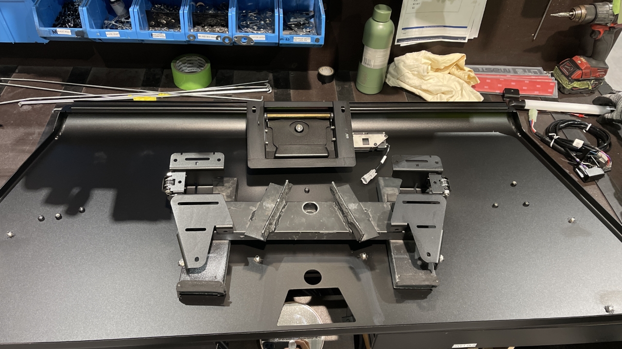
Check all 3 doors for defects and immediately send to rework if found any.
Apply surface activator on the UTEMASTER cut out.
Peel off branding backing plate and fit it on the cut out letters and press firmly. *Critical Quality Check: Make sure all letters fits evenly to the UTEMASTER cut out.

Prepare the brackets to be used for the door you are making including central locking parts if it is need to.

Countersink Side doors if needed before putting the door brackets. This applies on VWB3 canopy.

Apply surface activator on the brackets and to the door nearest to the studs.
Apply glue on the brackets

This is a critical step - ensure 6mm Glue bead and is applied in a pattern as shown here.
Place the handle and brackets to the door

Tighten the nuts to the studs

Using the mirror make sure the lock is centered.

Connect the central locking switch to the bracket
Connect the terminal to the actuator on the handle.

Make sure that the wiring is zip ties and away from the mechanism
Make sure that the cable are loosened not on tension giving allowance for door opening and closing to avoid any damage to the wires.
Install the designated rod for this model

*Critical Quality Check: insert foam on the center of the rods

Make sure rod is straight, not folded in between.

*Critical Quality Check: Make sure that the plastic pivot for rods is lock to prevent from coming off.
Put the required windlace seal if you are making the rear door
Attach the Cable cover and take out the LED Wiring Terminal.
Connect the terminals
Using M6x12 Black Bolts with pre-applied thread-locker. Install the lock cover and LED light bracket.
Critical Quality Check: Do not overtighten these bolts, the Thread locker will prevent these from rattling loose.
Put an extrusion to the the wires ready for the next assembly

*CQC Keep 120mm space for wiring loom from extrusion to door hinge

Use 220mm extrusion for rear door
Check branding logo fitted correctly.