
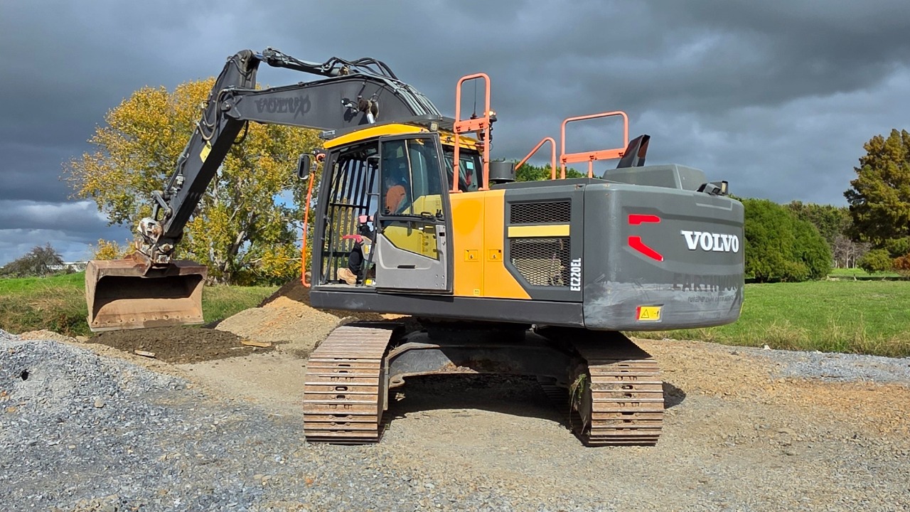

Important safety requirements
The inspection must be completed by a trained and authorised person.
Before starting:
Park the excavator on firm, level ground.
Lower the boom and attachment fully to the ground.
Place the controls in neutral.
Apply the safety lockout lever.
Turn the engine off and remove the key.
Allow the machine to cool before opening fluid compartments.
Maintain three points of contact when climbing onto or off the machine.
Do not place yourself beneath a raised boom or attachment.
If any items fail on this test, please notify either
Dave Mcgruer - 0272444548
Duncan Murray - 0212402859
Check the hydraulic oil level:
With the machine parked level and the Dipper arm fully extended with Bucket ram crowded and attachment lowered to ground level:
Locate the hydraulic oil level indicator.
Check that the oil is within the acceptable range.
Inspect around the hydraulic tank for leakage or damage.
Check that the cap and surrounding area are secure and clean.
Do not remove a hydraulic cap while the system is hot or pressurised.
Pass: Oil is within the indicated operating range with no visible contamination or leakage.
Fail: Oil is below the acceptable level, contaminated, leaking or the indicator cannot be read.
Check the engine oil level
Make sure the engine is off and has been allowed to sit before checking.
Open the engine access compartment.
Remove the engine oil dipstick.
Wipe the dipstick clean.
Reinsert it fully.
Remove it again and check the level.
Confirm the oil is between the minimum and maximum marks.
Refit the dipstick securely.
Pass: Oil is between the minimum and maximum marks and appears clean.
Fail: Oil is low, overfilled, contaminated or shows signs of water or metal particles.

Check the coolant level
Only check or open the cooling system when the engine is cool.
Inspect the coolant reservoir.
Confirm the coolant is between the minimum and maximum marks.
Inspect the reservoir, radiator area and hoses for damage or leakage.
Confirm the cap is fitted securely.
Never open a hot, pressurised cooling system.
Pass: Coolant is within the acceptable range with no visible leaks.
Fail: Coolant is low, contaminated or leaking.

Check the fuel level
Turn the machine ignition on without starting the engine and check the fuel gauge.
Confirm there is enough fuel for the planned work.
Also check:
Fuel cap is secure.
Fuel tank is not damaged.
There are no signs of fuel leakage.
Pass: Sufficient fuel is available and there are no leaks.
Fail: Fuel is too low for the planned work or leakage is visible.
Inspect the machine for leaks
Check underneath and around the complete machine.
Pay particular attention to:
Engine compartment
Hydraulic tank
Pumps
Control valves
Hydraulic hoses and fittings
Boom and dipper-arm cylinders
Tilt hitch and attachment hoses
Final drives
Fuel tank
Coolant system
Do not use your hands to search for pressurised hydraulic leaks.
Pass: No active leaks, wet fittings or significant fluid build-up.
Fail: Active dripping, spraying, pooling fluid or a fitting that is visibly wet.
Check the seat belt
Enter the cab using the access steps and handrails.
Inspect:
Seat-belt webbing
Buckle
Latch
Mounting points
Retractor operation
Fasten the belt and pull firmly against it to confirm it holds correctly.
Pass: Seat belt is undamaged, securely mounted and latches correctly.
Fail: Belt is cut, frayed, damaged, loose or does not latch and retract correctly.

Check the horn, travel alarm and quick-hitch buzzer
Before starting, make sure the area around the excavator is clear.
Start the machine in accordance with the normal start-up procedure.
Test:
Main horn
Travel alarm while carefully moving the machine a short distance
Quick-hitch warning buzzer using the approved hitch-testing procedure
Have another person stand in a safe, visible position if assistance is needed to confirm the travel alarm.
Pass: Each warning device operates clearly and correctly.
Fail: Any warning device is weak, intermittent or does not operate.

Check the beacon and work lights
Turn on each light individually.
Check:
Rotating or flashing beacon
Front work lights
Rear work lights
Boom-mounted lights
Cab lights
Any additional site lights
Walk around the machine and confirm each light is operating.
Pass: All required lights operate and lenses are clean and secure.
Fail: A light does not work, flashes incorrectly or has a damaged lens or mounting.
Check visibility from the cab
Clean and inspect:
Front windscreen
Side windows
Rear window
Mirrors
Rear-view camera lens
Camera display
Windscreen wipers and washers
Sit in the operating position and confirm there is a clear view around the machine.
Pass: Windows, mirrors and cameras provide clear visibility.
Fail: Visibility is obstructed or a mirror, camera, wiper or washer is damaged.

Check the fire extinguisher
Confirm:
Fire extinguisher is present.
It is securely mounted.
Access is not obstructed.
Safety pin and tamper seal are intact.
Pressure indicator is within the acceptable range.
Inspection or service date is current.
Cylinder and hose are not damaged.
Pass: Extinguisher is present, secure and current.
Fail: Missing, discharged, damaged, overdue or inaccessible.
Check the battery isolator and safety lockout lever
With the machine shut down, inspect the battery isolator.
Confirm:
Isolator is secure.
The switch operates correctly.
Labels are readable.
There is no damage or exposed wiring.
Then inspect the cab safety lockout lever.
Confirm:
Lever moves correctly.
Hydraulic functions are disabled when the lever is raised.
Hydraulic functions are enabled only when the lever is placed in the operating position.
Pass: Both devices operate correctly and are free from damage.
Fail: Either device is damaged, loose or does not isolate the machine as intended.
Check the interior switches, gauges and controls
Sit in the operating position with the seat belt fastened.
Check:
Instrument display
Warning lights
Fuel gauge
Temperature gauge
Hour meter
Joysticks
Travel pedals and levers
Throttle control
Wipers and washers
Heating, ventilation and demister
Emergency-stop or engine-stop controls, where fitted
Attachment and tilt-hitch controls
All other interior switches
Watch for warning messages after starting the engine.
Pass: Controls operate smoothly and no unexplained warning remains active.
Fail: A control sticks, does not work or an abnormal warning is displayed.

Inspect the lifting eye and D-shackle
Shut the machine down and isolate it before physically inspecting lifting equipment.
Check the lifting eye for:
Cracks
Distortion
Excessive wear
Damage around welds
Elongation of the lifting point
Missing identification or load markings
Check the D-shackle for:
Correct rating
Wear or distortion
Cracks or corrosion
Bent or damaged pin
Pin threading and secure engagement
Positive retaining device where required
Pass: Components are correctly rated, secure and undamaged.
Fail: Any cracking, distortion, excessive wear, missing markings or insecure connection.
Do not use damaged or unidentified lifting equipment.

Check lifting attachments and certification
Identify every lifting attachment and item of rigging used with the excavator.
This may include:
Chains
Slings
Shackles
Hooks
Lifting beam
Concrete-pit lifting equipment
Other lifting accessories
Confirm:
Each item has a readable identification number.
The working-load limit is visible.
Certification or inspection is current.
The item matches the lifting-equipment register.
Equipment is suitable for the planned lift.
Pass: Identification, working-load limit and certification are current and readable.
Fail: Certification is expired, identification is missing or the equipment is not rated for the lift.
Quarantine failed lifting equipment immediately so it cannot be used.
Inspect hooks, latches and connectors
Check every lifting hook, latch and connector.
Look for:
Cracks
Spreading or distortion
Twisting
Excessive wear
Corrosion
Damaged threads
Missing retaining devices
Safety latches that do not close fully
Pass: Hooks and connectors are secure, serviceable and close correctly.
Fail: Any component is cracked, distorted, excessively worn or unable to lock securely.

Inspect panel work, doors, guards and covers
Walk around the machine and inspect:
Engine covers
Side doors
Bonnet
Counterweight panels
Belly guards
Handrails
Steps
Access platforms
Latches and hinges
Open and close access doors to confirm they latch securely.
Pass: Panels, guards, doors and access equipment are secure.
Fail: A panel or guard is loose, missing, damaged or unable to latch.
Inspect the boom, dipper arm, tilt hitch and bucket
Check the complete front attachment from the machine outward.
Inspect for:
Cracks
Bent sections
Damaged welds
Excessive wear
Loose components
Impact damage
Missing bolts
Damaged hydraulic lines
Damage around pivot points
Pay particular attention to the lifting points and areas around welded joints.
Pass: Structures are secure with no visible cracks, distortion or serious damage.
Fail: Cracking, damaged welds, distortion or loose structural components are found.
Inspect the quick hitch and attachment connection
Inspect the tilt hitch or quick coupler.
Confirm:
Attachment pins are correctly engaged.
Locking mechanism is fully closed.
Safety device is engaged.
Pin-lock indicators show the correct status.
Hydraulic connections are secure.
There is no excessive movement or damage.
After connecting an attachment, perform the manufacturer-approved connection test before working.
Volvo quick couplers can include front-pin locking technology intended to help secure the attachment connection. The fitted coupler’s specific operating instructions must still be followed.
Pass: Attachment is positively locked and the safety system confirms engagement.
Fail: Locking position is uncertain, the warning remains active or the attachment has abnormal movement.
Inspect pins, bushes and retaining bolts
Check all visible pivot points, including:
Boom-foot pins
Boom-to-dipper pin
Dipper-to-hitch pin
Bucket pins
Tilt-hitch pins
Cylinder pins
Retaining bolts and locking devices
Look for:
Missing retainers
Loose bolts
Excessive sideways movement
Worn bushes
Dry joints
Metal debris around the pins
Pass: Pins and retainers are secure with no obvious excessive movement.
Fail: A retainer is missing, a bolt is loose or excessive movement is present.
Inspect hydraulic hoses, fittings and cylinders
Inspect hydraulic components throughout the machine.
Look for:
Cracked hoses
Abrasion
Exposed hose reinforcement
Kinked or crushed hoses
Loose fittings
Oil leakage
Damaged cylinder rods
Pitting or scoring on cylinder rods
Damaged hose clamps
Keep clear of pressurised components while the machine is running.
Pass: Hoses, fittings and cylinders are secure and leak-free.
Fail: Leakage, exposed reinforcement, damaged fittings or scored cylinder rods are found.

Inspect the tracks and undercarriage
Walk around both sides of the excavator.
Inspect:
Track chains
Track shoes
Shoe bolts
Rollers
Idlers
Sprockets
Final drives
Track guards
Track tension
Remove accumulated mud, concrete or debris where it is safe to do so. Volvo notes that failing to clean an excavator’s undercarriage can reduce its service life.
Pass: Undercarriage is secure, reasonably clean and track tension appears correct.
Fail: Loose track shoes, missing bolts, damaged rollers, oil leakage or abnormal track tension is found.
Check all grease points are lubricated and accepting grease
Complete this check with the machine parked on firm, level ground, the attachment lowered, the engine shut down and the key removed.
Locate all grease points shown in the Volvo EC220EL lubrication chart.
Wipe dirt and old grease from each grease nipple before connecting the grease gun.
Check each nipple for damage, looseness or blockage.
Connect the grease gun securely to the nipple.
Apply grease slowly until fresh grease is visible at the joint or normal resistance is felt.
Confirm the grease point is accepting grease and is not blocked.
Do not continue forcing grease into a nipple if pressure becomes excessive.
Wipe away excess grease after lubricating the joint.
Check for dry joints, unusual movement, damaged seals or metal particles in the old grease.
Record any grease point that will not accept grease and report it for repair.
Pay particular attention to:
Boom foot pins
Boom-to-dipper arm pin
Dipper arm-to-hitch pin
Bucket and attachment pins
Tilt hitch pivot points
Hydraulic cylinder pins
Lifting attachment pivot points
Any other points identified on the machine’s lubrication chart
Pass: All required grease points have been lubricated, accept grease normally and show no visible damage.
Fail: A grease point is blocked, damaged, missing, will not accept grease, or the joint remains dry or has excessive movement.
Important: Use the grease type and lubrication intervals specified in the Volvo EC220EL Operator’s Manual. Do not grease near moving parts while the machine is operating.
Carry out a controlled function test
After completing the physical inspection:
Make sure all access doors and covers are closed.
Enter the cab and fasten the seat belt.
Confirm the area is clear.
Start the engine.
Allow the machine to complete its start-up checks.
Check for warning lights, alarms or unusual noises.
Slowly test the boom.
Slowly test the dipper arm.
Slowly test the bucket.
Test the tilt hitch.
Test the slew function in both directions.
Carefully test forward and reverse travel.
Confirm all movements are smooth and controlled.
Check again for leaks after the test.
Pass: Functions operate smoothly with no abnormal noise, vibration, warnings or leakage.
Fail: Jerky movement, drifting, unusual noise, active warnings or leakage is detected.
Check service due hours
Turn the ignition on and check the current machine-hour reading on the display.
Check the recorded hours from the last completed service.
Confirm the next service due hours. This machine is serviced every 500 operating hours.
Calculate how many hours remain until the next service.
Confirm the machine is not within 10 hours of its next service.
Pass: More than 10 operating hours remain before the next scheduled service.
Fail: The machine is within 10 hours of its service, has passed the service due hours, or the service history cannot be confirmed.
Complete and submit the inspection
Once all checks are complete:
Mark each checklist item as passed or failed.
Add comments for any defect.
Attach photographs where useful.
Record any action already taken.
Submit the completed Knowby checklist.
The completed inspection should be provided to the Production Manager and filed in the agreed excavator inspection folder.