
To determine the side of the panel row, you will use the same rule.
For aesthetic reasons, you can choose to work further from the roof edge.
Use the same distance at the end of the row. This ensures the row aligns properly with the façade.
Hold the chalk line tightly along both markings. Pull it taut and snap the line to make the mark.
To mark a right angle, use the supplied square.
Use the square and a chalk line to make a vertical mark perpendicular to the horizontal marking.
Place a meter against the vertical marking. Now place a marking every 170 cm.
This is the same as the width of one panel. Now it's time to place the base units.
Make sure that you don't damage the roof with the end. On the front of each first panel, we attach protective end rubbers.
Remove the protective film on the self-adhesive side of the rubbers.
Stick the end rubber to the correct spot on the rail using the self-adhesive side.
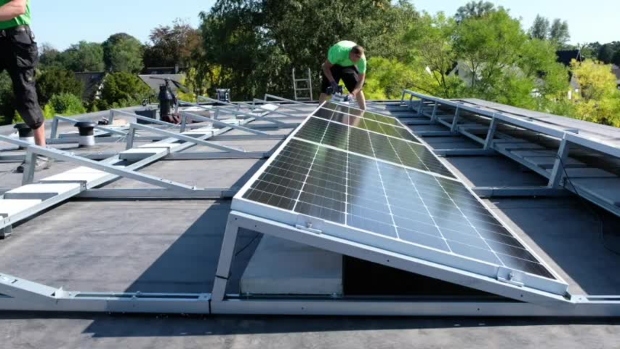
Carefully place the base units, equipped with protective end rubbers, onto the marked positions.
Slide the front into the rear rail of the unit in front.
Make sure that all units are neatly attached to each other in the holes provided for this with the included self-tapping screws.
Adjust the supplied spacer correctly.
Do this by placing it along the long side of a solar panel. Position the ends against the panel edges and tighten the screw.
After determining the correct distance between two base units, place two L-profiles between them, where a ballast tile will later be positioned.
Also for this, self-tappings screws are provided.
Double-check that all base units still align properly with the marked positions.
If everything connects nicely, also place the rest of the L-profiles and ballast tiles. Follow the provided ballast plan.
Try to place the tiles as close to the base units as possible.
Provide the necessary cables to connect your panels to the inverter.
The cables can be attached to the base units with zip ties.
Follow the provided string plan.
We ensure that our setup is grounded.
One cable is provided for grounding in the string plan. Strip the end of this cable and attach a cable lug.
Mark the grounding cable with heat shrink tubing or tape.
Secure the grounding cable to the base unit using a self-tapping screw.
Attach a connector to the string cables.
Use the connector crimping tool for this.
Push firmly until you hear a click, then hand-tighten the connector securely.
Apply ceramic grease to the spots where our panels will be mounted.
Watch out for damage. Never place a panel with its corner on the roof surface.
Remove the zip ties to release the connectors.
Secure the base unit to the base unit with clamps.
On the outside, you use end clamps.
Do not fully tighten the screws.
Between two rows you use middle clamps.
Place the next panels in the same way.
Once a full row is in place, you can fully tighten the end clamps.
Connect the panel with the cable closest to the inverter to this cable.
Secure the cables with a zip tie to the L-profile.
This way, the cables won’t end up lying in water.
At the back of each base unit, we install a backplate.
Place a back plate on the back of each base unit.
Let this plate rest in the designated groove and secure it with the self-tapping screws.
Congratulations, the task is done.
Now we can go inside.
We will attach the converter to the wall using a mounting plate.
You can test already how the converter will be attached to the mounting plate.
Using a spirit level, attach the mounting plate to the wall.
The direction of the arrow clearly indicates how the mounting plate should be placed.
Make sure there is enough free space around the converter.
The inverter can now be easily mounted to the wall.
The job is done!