
Knowby
Reassemble a Mk4 Renovator after shipping
1
Step 1 of 27
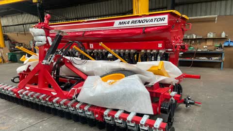
<p>Machine as unloaded</p>

Machine as unloaded

2
Step 2 of 27
<p>Fit axle stand to the side of the missing wheel to support the machine while its's being worked on</p>

Fit axle stand to the side of the missing wheel to support the machine while its's being worked on

3
Step 3 of 27
<p>Lift wheel assembly off the machine, it is heavy</p>

Lift wheel assembly off the machine, it is heavy

4
Step 4 of 27
<p>Lift axle assembly &amp; fit wheel, tighten wheel nuts to secure.</p>

Lift axle assembly & fit wheel, tighten wheel nuts to secure.

5
Step 5 of 27
<p>Lower drawbar and fit turnbuckle, tighten 1&quot;bolts until the nuts touch the center hitch profiles (top) and the side of the turnbuckle clevis (lower). As a starting point adjust the turnbuckle so the drawbar is Parrell to the machine chassis</p>

Lower drawbar and fit turnbuckle, tighten 1"bolts until the nuts touch the center hitch profiles (top) and the side of the turnbuckle clevis (lower). As a starting point adjust the turnbuckle so the drawbar is Parrell to the machine chassis

6
Step 6 of 27
<p>Fitting the lower Tee Boot assemblies</p>

Fitting the lower Tee Boot assemblies

7
Step 7 of 27
<p>The tines have been marked,
this mark should line up with the top of the Tee Boot</p>

The tines have been marked, this mark should line up with the top of the Tee Boot

8
Step 8 of 27
<p>Tee Boot in correct position
Tighten M10 bolts evenly until secure</p>

Tee Boot in correct position Tighten M10 bolts evenly until secure

9
Step 9 of 27
<p>The depth needs to be around a finger width from or 20mm from the clamp</p>

The depth needs to be around a finger width from or 20mm from the clamp

10
Step 10 of 27
<p>Replacing the Tine assembly that was removed for transport.
Slide the Tine through the Tine clamp &amp; line up with the mark on the Chassis
Tighten the two M16 bolts evenly until very tight.</p>

Replacing the Tine assembly that was removed for transport. Slide the Tine through the Tine clamp & line up with the mark on the Chassis Tighten the two M16 bolts evenly until very tight.

11
Step 11 of 27
<p>The seed hose will still be attached to the seed &amp; fertilizer boxes.
Feed the two hoses in between the coil tine and the chassis.</p>

The seed hose will still be attached to the seed & fertilizer boxes. Feed the two hoses in between the coil tine and the chassis.

12
Step 12 of 27
<p>Fit the seed &amp; Fert hoses,
The seed hose pushes all the way on and the Fert on about 60-75mm.</p>

Fit the seed & Fert hoses, The seed hose pushes all the way on and the Fert on about 60-75mm.

13
Step 13 of 27
<p>Finished assembly</p>

Finished assembly

14
Step 14 of 27
<p>All hoses fitted</p>

All hoses fitted

15
Step 15 of 27
<p>Start by fitting the footboard mount profiles
The two end profiles are fitted on the outside of the chassis rails, the two center profiles are on the inside of the Centre RHS</p>

Start by fitting the footboard mount profiles The two end profiles are fitted on the outside of the chassis rails, the two center profiles are on the inside of the Centre RHS

16
Step 16 of 27
<p>The outside footboard profiles are all bolted using M12 x 45mm bolts with flat washers against the profile, don't tighten bolts fully at this stage.</p>

The outside footboard profiles are all bolted using M12 x 45mm bolts with flat washers against the profile, don't tighten bolts fully at this stage.

17
Step 17 of 27
<p>The inside footboard profiles are bolted with M12 x 100mm bolts with flat washers against the slots, don't tighten bolts fully at this stage.</p>

The inside footboard profiles are bolted with M12 x 100mm bolts with flat washers against the slots, don't tighten bolts fully at this stage.

18
Step 18 of 27
<p>Lift the footboard into postion</p>

Lift the footboard into postion

19
Step 19 of 27
<p>The footboard sits onto the mount profiles as shown</p>

The footboard sits onto the mount profiles as shown

20
Step 20 of 27
<p>Fit bolts with flat washers on the slotted side.
Slide footboard all the way to the back of the slots and tighten bolts securely.
At this stage fully tighten the lower footboard mount profile bolts</p>

Fit bolts with flat washers on the slotted side. Slide footboard all the way to the back of the slots and tighten bolts securely. At this stage fully tighten the lower footboard mount profile bolts

21
Step 21 of 27
<p>Fit all the handrails &amp; M12 x 50mm bolts as shown to each end of the handrails.
The handrails are all bolted so they cannot be easily removed.</p>

Fit all the handrails & M12 x 50mm bolts as shown to each end of the handrails. The handrails are all bolted so they cannot be easily removed.

22
Step 22 of 27
<p>Handrail with drop lock needs to at the ladder end of the footboard</p>

Handrail with drop lock needs to at the ladder end of the footboard

23
Step 23 of 27
<p>Handrail bolts</p>

Handrail bolts

24
Step 24 of 27
<p>Lift the Footstep and mount into position.</p>

Lift the Footstep and mount into position.

25
Step 25 of 27
<p>Fit footstep M12 x 60mm bolts as shown &amp; tighten
Tighten M20 bolts until resistance is felt, step still needs to be able to move up and down easily.</p>

Fit footstep M12 x 60mm bolts as shown & tighten Tighten M20 bolts until resistance is felt, step still needs to be able to move up and down easily.

26
Step 26 of 27
<p>Ensure Ladder lock plate lines up with Drop lock as shown
If adjustment is required, loosen M10 Bolts, adjust then retighten.</p>

Ensure Ladder lock plate lines up with Drop lock as shown If adjustment is required, loosen M10 Bolts, adjust then retighten.

27
Step 27 of 27
<p>Check the seed drill has the required items for calibration, usually stored in the rear seed box
You should be good to go</p>

Check the seed drill has the required items for calibration, usually stored in the rear seed box You should be good to go