
Knowby
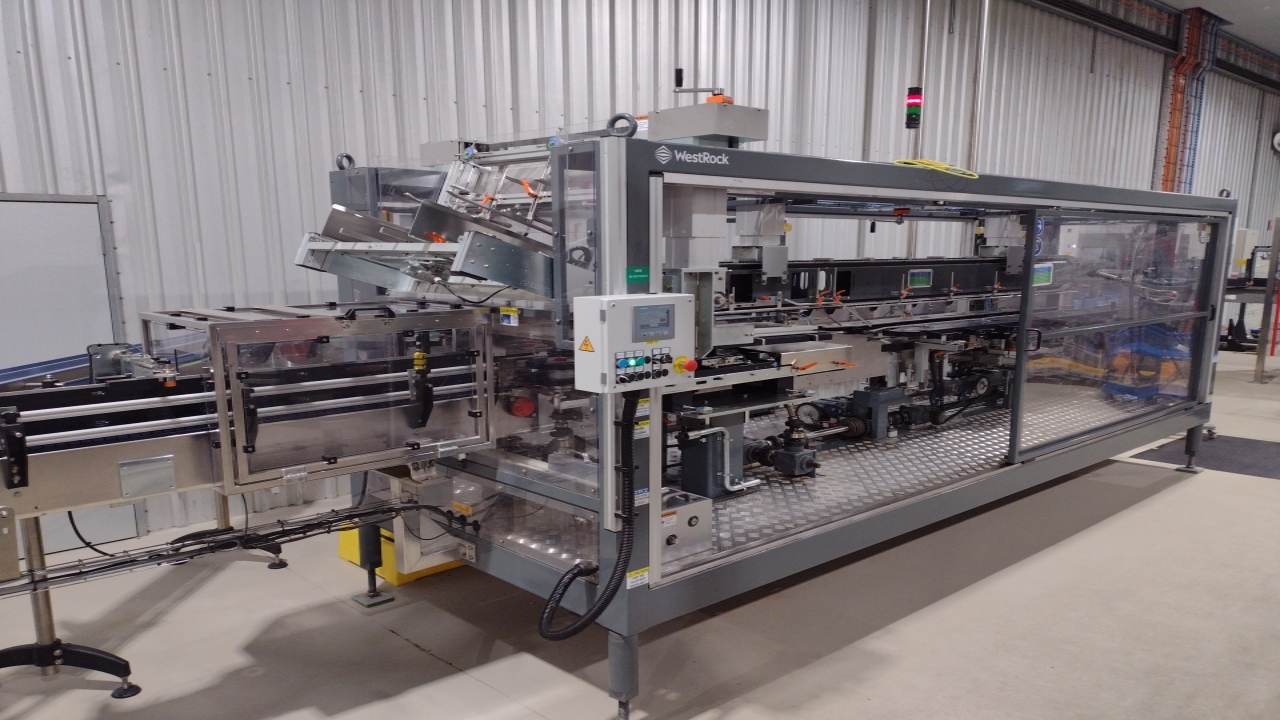
CP400 Size Change Process
Covers the steps required when completing a full size change on the CP400 Cluster packer. This document refers to PPM - ABC-PB9-008 Cluster Packer Operation.
1
Step 1 of 17

This process covers the size change of the CP400 packer.

Note: Some parts will not require change or movements. Always check the settings sheet before adjustments.

2
Step 2 of 17
<h2>Step 1 - Infeed Sensors</h2><ol><li><p>Loosen the locking handle</p></li><li><p>Move the Height dial to the correct format</p></li><li><p>Bring the support against the stop</p></li><li><p>Tighten the locking handle</p></li></ol><p></p>

Step 1 - Infeed Sensors

  1. Loosen the locking handle

  2. Move the Height dial to the correct format

  3. Bring the support against the stop

  4. Tighten the locking handle

3
Step 3 of 17
<h2>Step 2 - Hopper Height</h2><ol><li><p>Loosen the two locking handles</p></li><li><p>Move slightly the hopper upper retaining to the correct format</p></li><li><p>Bring the hopper upper retaining's against the stop</p></li><li><p>Tighten the two locking handles</p></li></ol><p></p>

Step 2 - Hopper Height

  1. Loosen the two locking handles

  2. Move slightly the hopper upper retaining to the correct format

  3. Bring the hopper upper retaining's against the stop

  4. Tighten the two locking handles

4
Step 4 of 17
<h2>Step 3 - Hopper Width</h2><ol><li><p>Loosen the two locking handles</p></li><li><p>Move slightly the hopper flanges to the select stop of the required format</p></li><li><p>Bring the hopper against the stop</p></li><li><p>Tighten the two locking handles</p></li><li><p>Repeat on both sides</p></li></ol><blockquote><p>Note: Magazine width needs to be set for both sides.</p></blockquote><p></p>

Step 3 - Hopper Width

  1. Loosen the two locking handles

  2. Move slightly the hopper flanges to the select stop of the required format

  3. Bring the hopper against the stop

  4. Tighten the two locking handles

  5. Repeat on both sides

Note: Magazine width needs to be set for both sides.

5
Step 5 of 17
<h2>Step 4 - Height Adjustment</h2><ol><li><p>Turn the adjustment wheel to display on the counter the height adjustment value for the required format.</p></li></ol><blockquote><p><strong>SAFETY</strong> - Use step to access adjuster</p></blockquote><p></p>

Step 4 - Height Adjustment

  1. Turn the adjustment wheel to display on the counter the height adjustment value for the required format.

SAFETY - Use step to access adjuster

6
Step 6 of 17
<h2>Step 5 - Gear Box</h2><ol><li><p>Open Gear Box safety cover</p></li><li><p>Unlock the index button (1) to unlock the index block</p></li><li><p>Using the Special tool (2) and using the crank handle (3) push or pull the index block (4) to the correct position and engage it into the synchronisation hub of the sprocket to the correct format</p></li><li><p>Lock the index button in the down position</p></li><li><p>Close the gear box safety cover</p></li><li><p>Place Tool back into position</p></li></ol><p></p>

Step 5 - Gear Box

  1. Open Gear Box safety cover

  2. Unlock the index button (1) to unlock the index block

  3. Using the Special tool (2) and using the crank handle (3) push or pull the index block (4) to the correct position and engage it into the synchronisation hub of the sprocket to the correct format

  4. Lock the index button in the down position

  5. Close the gear box safety cover

  6. Place Tool back into position

7
Step 7 of 17
<h2>Step 6 - Starwheels</h2><ol><li><p>Loosen the lower locking handles</p></li><li><p>Move the starwheel away from machine (Stops may need to be moved out of way)</p></li><li><p>Loosen locking knob on starwheel</p></li><li><p>Remove the starwheel and replace with correct one required</p></li><li><p>Install and tighten locking knob</p></li><li><p>Push starwheel frame back into machine</p></li><li><p>Select required stop to suit format and pull frame back against stop</p></li><li><p>Tighten locking handle on frame</p></li><li><p>Repeat for other side</p></li></ol><p></p>

Step 6 - Starwheels

  1. Loosen the lower locking handles

  2. Move the starwheel away from machine (Stops may need to be moved out of way)

  3. Loosen locking knob on starwheel

  4. Remove the starwheel and replace with correct one required

  5. Install and tighten locking knob

  6. Push starwheel frame back into machine

  7. Select required stop to suit format and pull frame back against stop

  8. Tighten locking handle on frame

  9. Repeat for other side

8
Step 8 of 17
<h2>Step 7 - Paper feed chains</h2><ol><li><p>Unscrew the two locking handles so they are fully loose</p></li><li><p>Push the paper feed chains slightly and set the stop to the format required</p></li><li><p>Pull the feed chains against the stops</p></li><li><p>Tighten the locking handles</p></li><li><p>Repeat steps for other side</p></li></ol><p></p>

Step 7 - Paper feed chains

  1. Unscrew the two locking handles so they are fully loose

  2. Push the paper feed chains slightly and set the stop to the format required

  3. Pull the feed chains against the stops

  4. Tighten the locking handles

  5. Repeat steps for other side

9
Step 9 of 17
<h2>Step 8 - Gripper Width</h2><ol><li><p>Loosen the two locking handles of the grippers</p></li><li><p>Move slightly the assembly to select the correct format</p></li><li><p>Bring the grippers against the stops</p></li><li><p>Tighten the locking handles</p></li><li><p>Repeat for both sides</p></li></ol><p></p>

Step 8 - Gripper Width

  1. Loosen the two locking handles of the grippers

  2. Move slightly the assembly to select the correct format

  3. Bring the grippers against the stops

  4. Tighten the locking handles

  5. Repeat for both sides

10
Step 10 of 17
<h2>Step 9 - Grippers</h2><ol><li><p>Unlock the index knob by pulling upwards </p></li><li><p>Slide out gripper to remove (if stuck a gentle tap with rubber mallet may be required)</p></li><li><p>Install new gripper and ensure index knob is locked in place</p></li><li><p>Use the Crank handle to slowly rotate machine to access all grippers </p></li><li><p>Repeat for all grippers on both sides</p></li></ol><blockquote><p><strong>SAFETY</strong> - Ensure all persons are back before rotating the machine</p></blockquote><p></p>

Step 9 - Grippers

  1. Unlock the index knob by pulling upwards

  2. Slide out gripper to remove (if stuck a gentle tap with rubber mallet may be required)

  3. Install new gripper and ensure index knob is locked in place

  4. Use the Crank handle to slowly rotate machine to access all grippers

  5. Repeat for all grippers on both sides

SAFETY - Ensure all persons are back before rotating the machine

11
Step 11 of 17
<h2>Step 10 - Adjust Boom side guides</h2><ol><li><p>Loosen locking handles</p></li><li><p>Move the height of the guide to the correct collar - tighten handle</p></li><li><p>Move the width to the correct collar - tighten handle</p></li><li><p>Continue along boom chain until all have been set</p></li><li><p>Repeat for both sides of machine</p></li></ol><p></p>

Step 10 - Adjust Boom side guides

  1. Loosen locking handles

  2. Move the height of the guide to the correct collar - tighten handle

  3. Move the width to the correct collar - tighten handle

  4. Continue along boom chain until all have been set

  5. Repeat for both sides of machine

12
Step 12 of 17
<h2>Step 11 - Overhead Chain</h2><ol><li><p>Check value required from the set points</p></li><li><p>Turn the handle until the counter matches the required value</p></li></ol><p></p>

Step 11 - Overhead Chain

  1. Check value required from the set points

  2. Turn the handle until the counter matches the required value

13
Step 13 of 17
<h2>Step 12 - Synch the Boom Chain</h2><p><em>Non- operator side</em></p><ol><li><p>Use a 13mm spanner to loosen the two locking bolts</p></li><li><p>Use black handles to rotate plate to bring the index in front of the value required</p></li><li><p>Use 13mm spanner to tighten lock bolts</p></li></ol><p></p>

Step 12 - Synch the Boom Chain

Non- operator side

  1. Use a 13mm spanner to loosen the two locking bolts

  2. Use black handles to rotate plate to bring the index in front of the value required

  3. Use 13mm spanner to tighten lock bolts

14
Step 14 of 17
<h2>Step 13 - Can Locker</h2><ol><li><p>Pull up the locking handle to unlock the bottle locker</p></li><li><p>Slide the bottle locker out</p></li><li><p>Loosen the two locking knobs and rotate out of position</p></li><li><p>Lift the bottle locker out of machine - Caution - Heavy</p></li><li><p>Collect new locker and line up pins and place into position</p></li><li><p>Rotate lock knobs back into position and tighten</p></li><li><p>Push unit in fully to machine</p></li><li><p>Lock slide in using the locking handle</p></li><li><p>Repeat for other side</p></li></ol><p></p>

Step 13 - Can Locker

  1. Pull up the locking handle to unlock the bottle locker

  2. Slide the bottle locker out

  3. Loosen the two locking knobs and rotate out of position

  4. Lift the bottle locker out of machine - Caution - Heavy

  5. Collect new locker and line up pins and place into position

  6. Rotate lock knobs back into position and tighten

  7. Push unit in fully to machine

  8. Lock slide in using the locking handle

  9. Repeat for other side

15
Step 15 of 17
<h2>Step 14 - Side Lug Chains</h2><ol><li><p>Loosen the two locking handles on the grippers</p></li><li><p>Move slightly to correspond for the new format</p></li><li><p>Bring the grippers against the stops</p></li><li><p>Tighten the grippers against the stops</p></li><li><p>Repeat for both sides.</p></li></ol><p></p>

Step 14 - Side Lug Chains

  1. Loosen the two locking handles on the grippers

  2. Move slightly to correspond for the new format

  3. Bring the grippers against the stops

  4. Tighten the grippers against the stops

  5. Repeat for both sides.

16
Step 16 of 17
<h2>Step 15 - Locking Section</h2><ol><li><p>Pull out the locking pins and slide locking section out</p></li><li><p>On locking wheel loosen the locking cam by loosing the bolt using an allen key</p></li><li><p>Slide out locking wheel and replace with new one</p></li><li><p>Line up the new locking wheel with grooves on back</p></li><li><p>Turn locking cam and tighten bolt</p></li><li><p>Slide locking section back into place, rear of section needs to line up with drive wheel</p></li><li><p>Push locking pins in to lock in slide</p></li></ol><blockquote><p>Note: If Slide is not lined up properly you will not be able to lock it in</p></blockquote><p></p>

Step 15 - Locking Section

  1. Pull out the locking pins and slide locking section out

  2. On locking wheel loosen the locking cam by loosing the bolt using an allen key

  3. Slide out locking wheel and replace with new one

  4. Line up the new locking wheel with grooves on back

  5. Turn locking cam and tighten bolt

  6. Slide locking section back into place, rear of section needs to line up with drive wheel

  7. Push locking pins in to lock in slide

Note: If Slide is not lined up properly you will not be able to lock it in

17
Step 17 of 17

Work complete.

Close all doors and reset machine.

Check operation carefully when running the first packs through machine.

For further Information on running the machine see:

ABC-PB9-008 Cluster Packer Operation.