
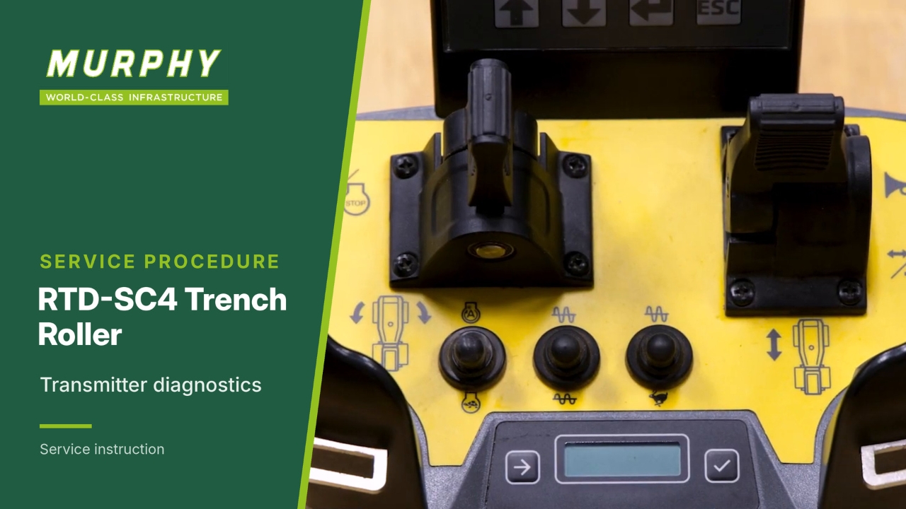
Turn the transmitter on
Turn the transmitter on by twisting the emergency stop (the emergency lock function).
Enter diagnostic mode
The information screen is on the bottom of the transmitter, with two push buttons.
Push both push buttons at the same time, then let go. This enters diagnostic mode.
Press the enter button.
What you can test
You can now test several functions on the transmitter:
Analogue actuators: the left/right paddle and the forward/reverse paddle.
Digital actuators: the toggle switches and push buttons.
Open the analogue actuator test
To test the analogue actuators first, press the enter button and watch the values on the information screen.
Top line: actuator identification.
Bottom line: binary value of the actuator position.
Test the left/right paddle
Push the paddle to the left. The identifier is 01S: 01 is the left actuator and S means it is a safety actuator. 127 represents 100% position.
Return it to neutral. 0 represents the neutral position.
Push it all the way to the right. It should again read 127.
A reading from 0 to 127 means a good functioning actuator.
Test the forward/reverse paddle
Pull the paddle backwards (down). The identifier is 02S: 02 is the forward/reverse paddle (the right actuator) and S means it is a safety actuator. The 100% value is 127.
Return it to neutral: 0.
Push it forward (up): 127.
The analogue actuators are now tested.
Open the digital actuator test
Navigate down to menu 1.2.
Press the check mark.
You can now activate the toggle switches and push buttons on the transmitter.
Test the engine speed switch
Activate the engine speed toggle switch and watch the values on the left side of the information screen.
Low engine speed = 02
High engine speed = 03
Toggle from low to high and back to low. If the value changes from 02 to 03 and back to 02, the toggle switch is good.
Test the vibration switch
Do the same for excitation (vibration).
Low excitation = 04
High excitation = 05
If the value changes, the toggle switch is working.
Test the travel speed switch
Low travel speed = 06
High travel speed = 07
If the value changes from 06 to 07, the toggle switch is functioning.
Test the three push buttons
Press each momentary push button and watch the value change:
Engine start = 01
Steering mode = 19
Horn = 08
If the values change, the three push buttons are functioning.
Page 1.3: rotary encoder
The information screen has additional diagnostic pages for the transmitter.
Page down to 1.3, the rotary encoder. This is not used on RTD-SC4 trench rollers.
Page 1.4: pitch and roll angle
The next page, 1.4, shows the pitch and roll angle of the transmitter, and impact.
A pitch and roll angle sensor is built into the transmitter. It can be read on the diagnostic screen to make sure this function works.
Read the pitch and roll values
Press the enter button to read the current position of the transmitter.
Turn the transmitter left, then right. The angle values change.
Roll it forward and backward. The values change again.
If the values change, the function is working.