

Field Locker link -
All employees and contractors approaching these structures shall first ensure by
means of a visual inspection and a “Safe-to Approach” test prove that the
transformer HV Earthing System is not at a dangerous potential.
The transformer shall not be accessed if during the initial visual inspection any
one of the following signs are observed:
• Broken or missing HV earthing connections on pole and/or transformer.
• Signs of vegetation near the pole either drying out or dying (in comparison
with surrounding vegetation).
• Smoke or steam rising from ground near transformer; or
• The Safe – to Approach test shows up positive

While standing 6 metres away from the SWER Isolating Transformer, SWER-Transformer or capacitive balancing Unit:
• Undertake a visual inspection of the pole
• Need a clear view of the overhead conductors
Underneath the HV Line & inline with the earth is ideal
• Trees and LV power lines interrupt the signal to the Mini SWER tester
Where the signal is blocked stand at right angles to the line & pole to enable detection of the high voltage SWER line or assets

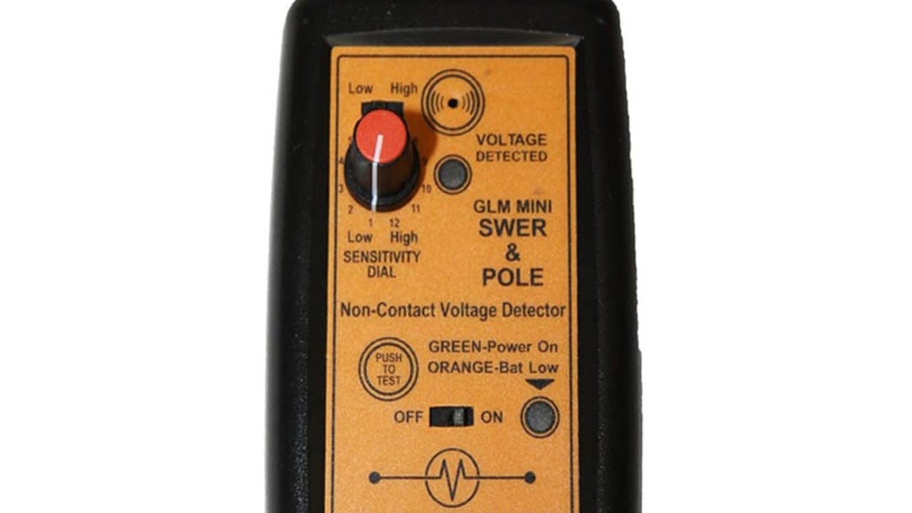
Performing self-testing
• Check that the sensitivity switch is set to high
• Check the sensitivity dial is set to high (12)
• Switch unit to the “ON” position
• Confirm the low battery LED is still GREEN
Note: If ORANGE/RED LED illuminates, replace battery.
• Press the Self-Test Button to check the unit is operating correctly.
The tester is verifying
• Audio indicator
• Visual indicator
• Battery condition
• Transistor circuit verification.

Calibration procedure
• With the Test Area top side of the unit facing the voltage line to test, place your thumb on Place Thumb Here area
Warning do not touch the self-test area at the front of the unit
• With arm outstretched, this allows maximum detection distance (the closer the unit is to the trunk of the body, the lower the detection distance).
Adjust the sensitivity of the Mini SWER & Pole tester
• Raise the tester above the head and adjust the sensitivity dial until the voltage in the line above is detected.
• Lower the tester to the chest height. At this position no alarm should be heard the overhead field is broken and the approach to the pole can be made.
• If the detector continues to alarm at chest height, adjust the sensitivity (lower)then raise the unit above the head again (tester will alarm)
• Lower the tester to the chest height. At this position no alarm should be heard the overhead field is broken and the approach to the pole can be made.
Note: If the detector still sounds the alarm, there is possibly voltage in the ground, do not continue.
• Warning, if an alert is heard, repeat test to verify findings, if alert is heard the second time, do not continue proceed any further.
• Contact your Field Leader/ CPL/ Control room and report the situation.
If no alarm is sounding approach the pole
• Point the mini SWER tester test area towards the ground
• While moving the tester from side-to-side if no alarm is sounding approach the pole
• Warning, if an alert is heard, repeat test to verify findings, if alert is heard the second time, do not continue proceed any further.
• Although not shown in the video it is advisable stop after 3 meters and raise the tester above your head to verify the tester is still operating
• Lower the tester to chest level and verify that there is no alarm at chest level, adjust the sensitivity as required is heard.
• While moving the tester from side-to-side if no alarm is sounding approach the pole
• Point the mini SWER tester test area towards the ground
• Warning, if an alert is heard, repeat test to verify findings, if alert is heard the second time, do not continue proceed any further.
• Move the tester to around 25mm from the pole. If there is no alarm, there is no significant voltage on the pole.