
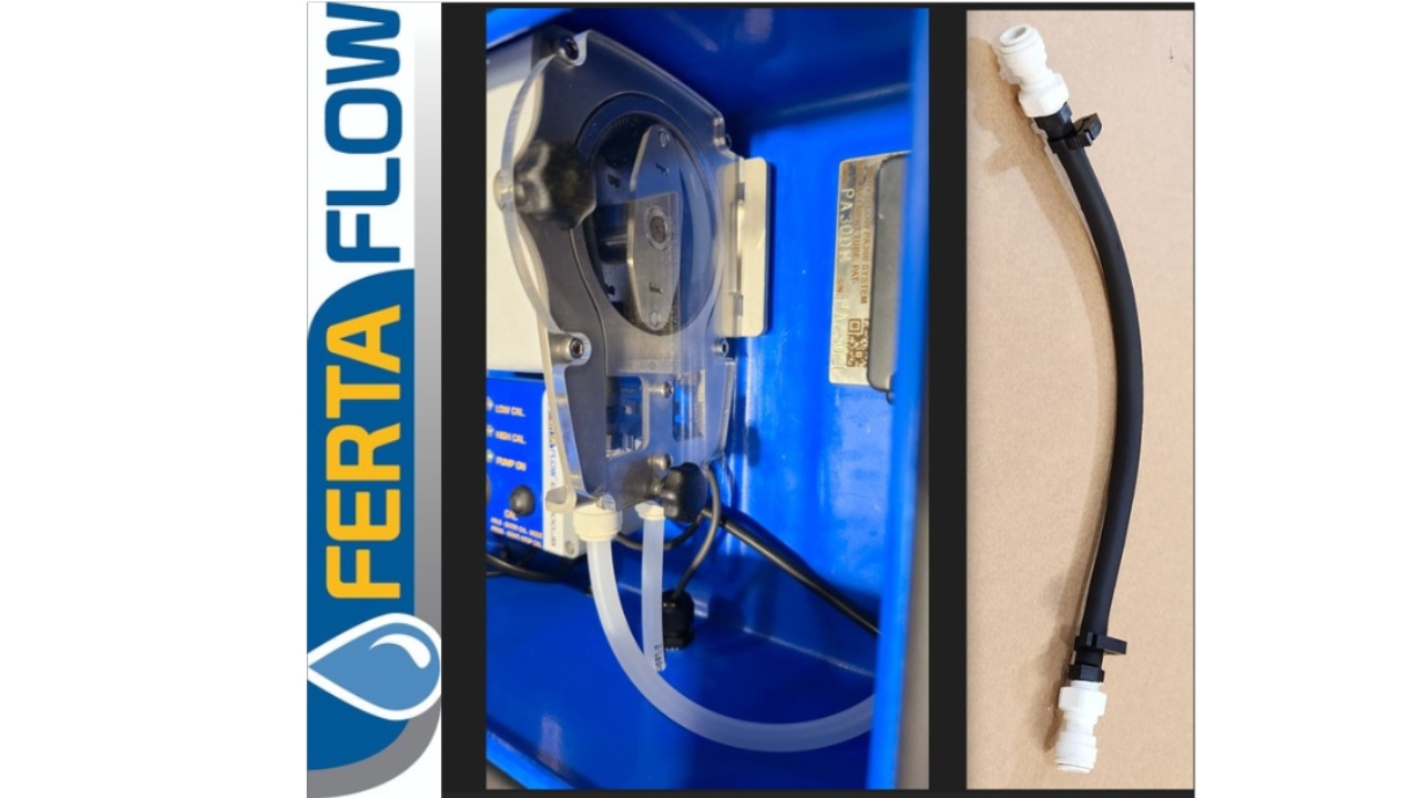

Tube Change over for PA300 Pump
Items: Spare Tube (options below)
Code: PAT-1 (300mL/min Max Flow)
Code: PAT-2 (620mL/min Max Flow)
Code: PAT-3 (1250mL/min Max Flow
Tools required: None

Disconnect the Fluid Lines
Remove the fluid inlet and outlet lines by lifting the locking ring on the white push-fitting and pulling out the tube at the same time.
Locking Rings shown in Green
Tubes to be pulled out in yellow.
Removing the lines
If necessary, use a set of long nose pliers to lift the locking ring (sometimes fingers aren't very effective if wet)
Remove the Cover
Remove the clear pump head cover by undoing the 2x black knob screws
Then pull the cover out from the lock tag at the rear.
Remove the Tube
Rotate the rotor to verical and unclip the tube and peel out the tube towards the top
Continue to turn the rotor 180 degrees while removing the tube until the other end is free.
Unclip the tube and remove from the pump head.
Install the tube
Position the rotor vertical and clip in the tube on one side. Feed in the tube to the top.
Turn the rotor while feeding in the tube behind it, until the rotor has done 180 degrees and is vertical again.
NOTE: Ensure the black clips on the end of the tube are facing towards motor (away from the clear cover to allow it to clamp against the flat of the white hex fittings on the ends.)
Replace the front cover
Insert the clear cover in to the locking tabs and fold onto the pump head face.
Ensure the tube is not protruding out from the rotor and the black plastic tube clamps are facing away from the cover.
The white hexagonal fittings should be clipped into the locationg grooves and the flats sitting parallel with the cover.
Locate the knob screws in the holes and tighten up the cover onto the stainless frame.
Replace the fluid lines
Insert the inlet and outlet tubes into the pump head push-fit connectors as shown.
Ensure they go right in to seal on the internal O-ring.
Failure to seal will cause loss of prime on the inlet or leaks on the outlet, into the enclosure.
Test Run the new Tube.
Conduct a volume/time test with the controller on full to establish the Maximum Flow Rate.
Then do the same at the Minimum Flow Rate.
Compare this to the rate on the EFM metering display in mLs/min
If there is significant variance, proceed to recalibrate the system.