
Glass Outlet
Critical Risk Standard No.1 Hazardous Energy Control. -Awareness
A de-energized state occurs when equipment is physically isolated from all energy sources and does not contain residual or stored energy. The unexpected release of hazardous energy is not possible.
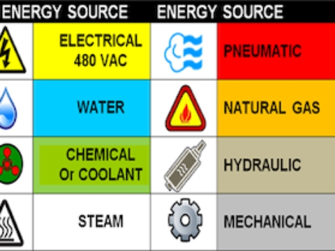
3.5 Energized Connected to an energy supply/source or containing residual or stored energy. Energy can be in any form potential or kinetic and may include but not limited to the following sources:
gravity,
pneumatic,
hydraulic,
or chemical sources.
3.6 Energy Isolation Device An energy isolation device is a mechanical device that physically prevents the transmission or release of hazardous energy.
Examples include electrical disconnects, circuit breakers, valves, blank flanges, and blocks or pins used to isolate stored energy sources such as gravity.
Push buttons, selector switches, hydraulic/pneumatic block and bleed valves and other control circuit type devices are NOT energy isolation devices and may not be used for energy control.
A positive means such as a cable, valve cover, or circuit breaker adaptor that secures an energy isolating device in the safe position. A lockout device allows a lock to be attached to the energy isolation device. A lockout device may also be referred to as a lockout adaptor.
DO NOT use an Emergency Stop as an energy isolation device. It may fail and is designed for emergency conditions.
3.7 Exclusive Control
Exclusive control means that the machine operator maintains the only means to start a piece of equipment or process. For example, an operator’s body blocking a light curtain would prevent machine activation assuming that the light curtain has the required circuit logic. On the other hand, opening an interlocked door on a machine and climbing into the machine does not provide the operator with exclusive control of the means to start the machine if the door can be closed behind the operator.
This term is used in conjunction with minor servicing or operational tasks that are routine, repetitive and integral to the operation of a machine during normal production operations.
Example - Jog control in use and no other present.
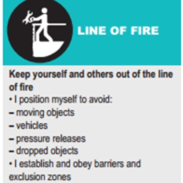
Line of Fire – Summary
Meaning:
Being in the path of moving energy — where you could be hit, crushed, caught, burned, or struck if something moves or releases unexpectedly.
Common Hazards:
Struck-by: tools, vehicles, falling objects.
Caught-in/between: moving parts, pinch points, suspended loads.
Energy release: pressure, electricity, gravity.
Thermal/Chemical: hot surfaces, steam, splashes.
Main Causes:
Working too close to moving or pressurised systems.
Not isolating energy sources.
Poor communication or awareness.
Controls:
Isolate energy before work.
Stay clear of moving parts and suspended loads.
Use guards/barriers.
Keep good communication and visibility.
Stay alert — always know where the danger line is.
Key Point:
Isolation removes the energy that puts you in the line of fire.
3.13 Operational Zone The operational zone is any area on a piece of equipment or process where injury could result if the equipment or process were to start or release energy in an unexpected manner.

3.15 Safeguard A safeguard is a physical barrier or electronic device that prevents access to areas of the machine, equipment or process where a hazard exists.
3.16 Servicing and Maintenance Servicing and maintenance includes activities such as constructing, installing, modifying, dismantling, setting up, changing tools, adjusting, inspecting, lubricating, cleaning, unjamming, and troubleshooting. Maintenance and servicing tasks may be performed by either maintenance or production personnel.
3.17 Shall or Must The words SHALL or MUST indicate mandatory requirements.

3.18 Stored Energy Stored energy is a potential hazard that still exists after a primary energy source has been locked out. For example, a pump motor for a hydraulic system may be locked out, effectively stopping fluid flow, but energy in the form of hydraulic pressure may still exist in the machine or hydraulic line. This pressure must be released before work proceeds.
Hazardous energy control requires that all stored energy be controlled to ensure complete zero energy state.
Example - Compressed air line will be at pressure and held when compressor is off.

4.3.2 Upon completion of the task analysis, ALL sites must develop equipment-specific lockout procedures or isolation plans for each piece of equipment at the site based on the ALL template held in Safety Champion / Skytrust
Written procedures are not required for cord and plug-connected equipment and pieces of equipment that have single, readily identifiable energy isolation devices if there is no potential for stored energy after shut down.
A lockable plug cover must be installed on plug-connected equipment and a personal lock placed on the cover.
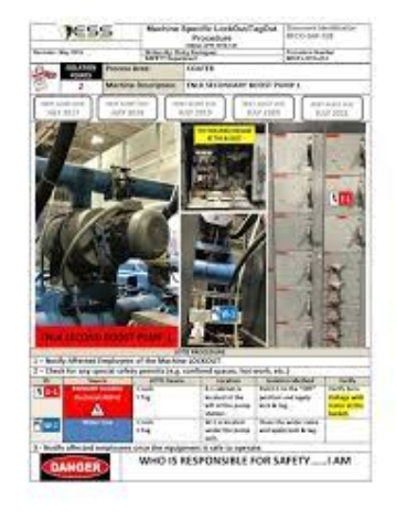
4.3.3 Equipment-specific lockout procedures must contain critical information as per the Company standard.
4.3.4 Equipment-specific energy control procedures shall be readily accessible near the applicable piece of equipment and shall be contained in the area information centers.
4.3.5 Sites shall maintain an inventory of all equipment-specific lockout procedures on Safety Champion / Skytrust and follow the systems document and record control procedures to ensure compliance.
4.3.6 New equipment or processes may not be placed into service until equipment-specific lockout procedures are developed and made accessible to authorized persons.

When zero energy state is not feasible during serving and maintenance activities and team members are exposed to hazards of energized equipment, the Partial Energy Work Permit must be utilized.
The permit must state in observable terms how the task will be performed safely to ensure that persons remain safely positioned away from the operational zone during the troubleshooting task.
Examples include:
▪ Positions of employees
▪ Placement of barricades
▪ Special tools
▪ Inspection cameras
▪ Partial lockout
▪ Machine safeguarding
Partial energy work permits may be pre-printed for common tasks that require a piece of equipment to be partially energized such that employees are exposed to the hazards of energized equipment.
.
Prior to performing the task, the permit must be reviewed and signed by the persons performing the task and the appropriate supervisor.
The Queensland Electrical Code of Practice 2013 – Managing Electrical Risks in the workplace must be followed as referenced in part in the legal requirements section above

4.4 Use of Locks
4.4.1 The use of tags without locks is not permitted for energy control. In the event that an energy isolation device cannot be locked, a lockout adaptor that will accept a lock shall be utilized or a lockable energy isolation device located upstream of the process shall be utilized.
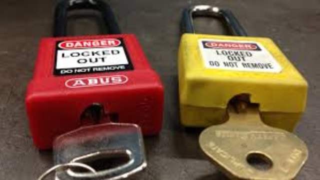
4.4.2 Locks used at Group sites shall be standardized by color and manufacturer as per Company standard Appendix A and only site locks shall be used for isolation and controlled by the site Sustainability Coordinator or delegate.
4.4.3 Locks issued for lockout may not be used for any other purpose such as securing tool boxes or personal lockers.
Example of personal Danger lock being used to lock

4.4.4 All employees working on a piece of equipment must affix a lock to the energy isolating devices identified in the applicable equipment-specific energy control procedure. Employees or contractors shall not work under the protection of another person’s lock.
4.4.5 Locks may only be removed by the person who placed the lock. In the event that a lock is left on an energy isolating device and the person to whom the lock belongs has not left the site, the person must be located to remove the lock.
If that the owner of the lock has left the site, a supervisor will:
▪ Attempt to contact the owner of the lock including calling the owner if necessary;
▪ Inspect the equipment to ensure that it is operationally intact and safe to operate; ▪ Obtain approval to remove the lock from the site manager;
▪ Cut the lock;
▪ Document the lock removal on a Lock Removal Authorization Form; and
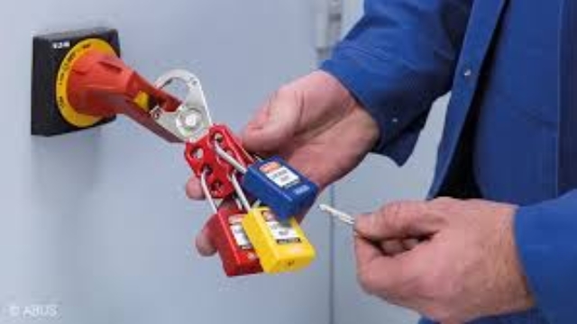
4.4.6 Once a piece of equipment is to be re-energised the activity and lock transition procedure below shall be followed to ensure there is an orderly transfer of locks so that a piece of equipment is never left in an unsecured state.
1. Check job is complete and personnel are clear
2. Ensure all equipment is safety re-attached to machine
3. Ensure controls are all in the off position.
4. Remove lockout devises and reenergize machine.
5. Perform a functional test of the machine
6. Return locks to isolator cabinet & hand permit back
A declaration statement will be made and signed and handed back to the Control of Work controller which is the Sustainability Coordinator or delegate.

4.4.7 Group lockout procedures should be used when multiple authorized persons are working on complex machines or processes with more than three (3) sources of hazardous energy or when energy isolation devices are not readily accessible such as electrical disconnects located inside an electrical enclosure.
Examples of complex machines include boilers, acid recovery systems, automated painting lines, and tube mills.
The Group lockout procedure is provided in Appendix B. Although the group lockout procedure can be used for equipment with less than three (3) sources of hazardous energy, authorized persons can typically apply a lock hasp to each energy isolation device when working on non- complex equipment with multiple energy sources.
Each person working on the locked out equipment will then place their personal lock(s) on the lockout hasp(s).

4.5 Line Breaking 4.5.1 Each ALL site shall maintain an inventory of hazardous substance process lines as part of their site-specific hazardous energy control training program and this is held within Safety Champion.
4.5.2 A line breaking permit shall be utilized before opening any hazardous substance process line. The permit must be signed by the supervisor in charge of the area and each person involved in the line breaking activity.
Line breaking procedure is provided in Appendix C & is available on the Control of Work board.

4.6 Periodic Inspections 4.6.1 Periodic inspections shall be conducted at least quarterly in accordance with the quantities specified below.
The purpose of quarterly inspections is to serve as a “spot check" to verify that the lockout program continues to be deployed properly. This will be conducted by the site Program Champion and/or Sustainability Coordinator and shall be scheduled within Safety Champion for completion and tracking.
4.6.2 Each inspection must include a review of the written equipment-specific lockout procedure, observation of an authorized employee using the procedure, and identification of any corrective actions required to address deficiencies identified during the inspection. Inspections must be conducted by an authorized employee not directly involved in the task being evaluated and must address all shifts and departments.

4.7Contractors
4.7.1 The Glass outlet employee coordinating the contractor’s activities will supply contractor management with a copy of the applicable equipment-specific lockout procedure(s).
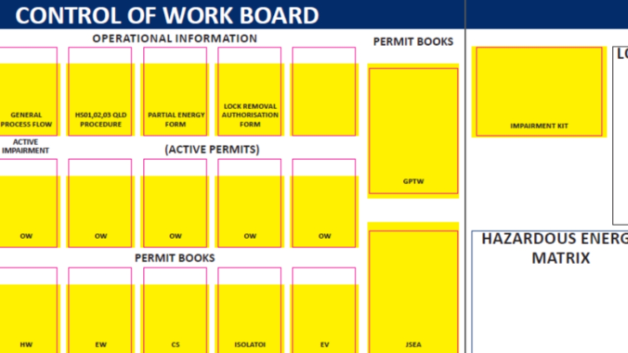
They are to utilize the site Control of Work board to manage work processes within these guidelines.

4.7.2 Equipment will be locked out using a blue out of service lock and the item will be functionally tested by an authorized Group employee.
Each contractor employee will then be required to install their personal locks on the appropriate energy isolation device prior to starting a job.
Control of Contractors and on-site maintenance work shall be controlled through the effective use of the Control of Work Board which details all relevant information and procedures to manage site work flow and meet this standard.

4.8 Training
4.8.1 New employees and contingent (temporary) workers must receive awareness training as part of their onboarding training through the site induction.
4.8.2 Authorized employee candidates must receive classroom training prior to assignments that require the use of lockout.
4.8.3 At the conclusion of the classroom training, authorized employee candidates shall complete an exam. Employees must score at least 90% on the exam.
Employees who score less than 90% will be required to review the incorrect answers with the instructor.
Upon completion of this review, employees will complete a second exam. Employees who do not achieve a score of at least 90% on the written exam may not be assigned to jobs that require application of lockout.
4.8.4 Authorized employee candidates who pass the written examination must complete a verification of proficiency as part of the initial training process.
The verification of proficiency will consist of the candidate demonstrating lockout on an actual piece of equipment to his/her supervisor. The supervisor will select a lockout procedure that represents all of the different types of hazardous energies that may be encountered by the candidate. The verification of proficiency must be documented on a Verification of Proficiency form available in Safety Champion.
4.8.5 Authorized employee proficiency in the use of energy control will be verified on an annual basis for each authorized employee. The verification of proficiency will be documented on a Verification of Proficiency form, this shall be scheduled on the Safety Champion monitoring and measurement ‘compliance calendar’.
4.8.6 Authorized employees shall receive refresher training whenever process changes render previous training obsolete; or workplace observations indicate that persons have not retained an understanding of the skills required by this Standard. Absent of these specific requirements, refresher training shall be provided every 36 months.
4.9 Records Retention
The documentation listed below must be maintained in accordance with the retention periods listed below or as required by applicable regulatory requirements and shall be held on Safety Champion.
▪ Site-specific hazardous energy control procedure – until superseded
▪ Equipment-specific lockout procedures – until superseded
▪ Training records – until superseded ▪ Verification of proficiency – until superseded
▪ Partial energy work permits – 1 year ▪ Line breaking permits – 1 year ▪ Lock removal forms – 1 year

BLUE locks are used to lockout equipment or circuits that are temporarily out of use. These locks may not be used for personal protection.
Each lock will be equipped with a NOTICE tag similar to the one pictured below.
Blue locks will be keyed-alike.
Keys will be maintained by the maintenance department.

RED locks indicate that an energy source is locked out by a Group authorized employee who is performing servicing or maintenance activities on a piece of equipment.
Each lock shall be keyed differently.
Spare keys will not be maintained.
Each lock shall be equipped with a tag or decal affixed directly to the lock body. The tag or decal must contain the following information in the local language used to conduct business at the site:
Each lock shall be equipped with a tag or decal affixed directly to the lock body.
The tag or decal must contain the following information in the local language used to conduct business at the site:
DANGER – Locked Out – Do Not Remove Employee’s name Employee identification number

Example tag - DANGER – Locked Out – Do Not Remove Employee’s name Employee identification number


Each lock shall be equipped with a tag or decal affixed directly to the lock body. The tag or decal shall contain the following information:
▪DANGER – Locked Out – Do Not Remove Group Lockout Lock
▪These locks shall be keyed individually with only one key.
The tag or decal shall contain the following information:
DANGER – Locked Out – Do Not Remove Lockbox Hold Lock
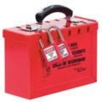
Appendix B – Group Lockout Procedure
The group lockout procedure is used when multiple authorized persons are working on complex machines or processes with more than three (3) sources of hazardous energy or when energy isolation devices are not readily accessible such as electrical disconnects located inside an electrical enclosure.
A lockout authorized supervisor will place GREEN locks on each energy isolation device identified on the equipment-specific lockout procedure.
Step 2
The supervisor will verify zero energy state as outlined on the equipment-specific lockout procedure.
Step 3
After verification of zero energy state, the keys for the GREEN locks will be placed inside of a lockbox.
Step 4
The supervisor will place a YELLOW lock on the lockbox. The purpose of this lock is to ensure that the lockbox is never left in an unsecured state when authorized persons remove their personal locks from the lockbox.
Step 5
Each person working on the equipment or process will place their RED lock on the lockbox.
Step 6
When additional authorized persons join the job in progress, the equipment needs to be cleared of personnel so that the newly arrived employee(s) can verify zero energy state in accordance with the equipment-specific lockout procedure.
Lockbox

Appendix C - Line Breaking Procedure
Preparation Activities
1. Review the SDS for the hazardous substance and identify the required personal protective equipment. A face shield and goggles are the minimum required PPE for all line breaking activities.
2. Notify employees working in the area that a line breaking will be performed.
3. Determine the direction of flow and system pressure. Assure that all system sources and accumulation points have been identified and are addressed by the pressure relief process.
4. Barricade the job area including any lower levels in order to keep employees working in the area away from the potential hazards.
5. Test the nearest safety shower and eyewash unit for proper function. If a safety shower is not available, a temporary means to provide drenching capability with potable water must be provided.
6. Drain and relieve any residual pressure from the line. This can be accomplished by releasing fluids and pressure back into a holding tank.
7. Use RED locks to lockout the electrical energy to pumps and blowers that serve as the prime mover for the hazardous substance.
8. Close and lock the valves on either side of the break-in point using RED locks.
9. If the line is equipped with a drain or bleed valve, open and lock the valve using RED locks. Place a bucket or catch basin under the break-in point to catch any residual substance that may still be in the line.
Break-In Activities
1. Obtain a line breaking permit. The permit must be fully completed and signed by the supervisor in charge of the area and each person involved in the line breaking activity.
2. A second authorized employee must be present during the initial break-in activity to verify that all preparations were completed. The second person must wear the same personal protective equipment as the person making the break-in.
3. Place a bucket or catch basin under the break-in point to catch any residual substance that may still be in the line.
4. To minimize contact as a result of spray-out of a hazardous substance, joints on pipes should be covered with plastic sheeting or a towel.
5. Put on all required protective equipment.
6. Slowly open the line. Do not stand directly under or over the break-in point.
Return-to Service Activities
1. Complete a visual examination of the repair or modification to ensure that all bolts, flanges, and lids are tight and sealed properly. Apply a bubble solution to flanges and joints on lines conveying gas substances to identify leaks.
2. Return completed line breaking permit to site EHS coordinator.