

Tools Required
Multimeter with DC Voltage measurement
PH0 Phillips Screw Driver
PH2 (#2 Phillips) Screw Driver
or PH2 Driver in a power drill.

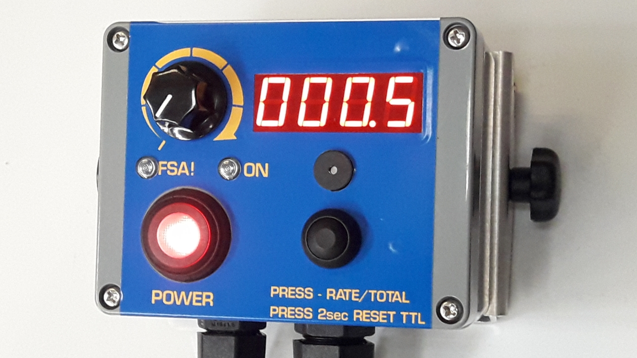
Remove the Front Cover of Cab Controller
Use the #2 Philips Driver to undo the 4x screws in each corner on the front of the controller.

Open up the front cover
Carefully open, ensure the lid seal doesnt come out if its groove.
Open enough to gain acess to the adjustment potentiometer (yellow arrow)
And allow the multimeter probes to measure the crew heads on the brown and blue pump power output terminals. (black and red arrows)

Power up the Pump
Turn the front speed dial anti-clockwise so it is on minimum
Ensure the pump is running (Power ON and Switched to Manual at the applicator)
Be careful not to touch or short any components on the PCB inside the controller

Measure the Existing Min. Output Voltage
Set the Multimeter to DC and place the probes on the Brown (+12V) and Blue/White (Regulated Ground) Pump Power output terminals.
This should measure either:
7.0Vdc for FA600 Series Applicators
6.0Vdc for PA200 Applicators
or 5.5Vdc for PA300 Applicators.

Adjust the Potentiometer
Carefully adjust the potentiomer to the desired voltage as the pump is running.
Hold the probes on the output terminals while you watch the multimeter display
Rotate anticlockwise to reduce the voltage, It is very sensitive and the smallest rotation will change voltage a lot.
Factory setting for the new PA302 pump is 4.5Vdc (35-100% range) but 4.0Vdc is allowable.
Reducing this too far will reduce the maximum voltage achievable at the top of the flow range and increase the chance of the pump stalling.

Close the Cab Controller
Carefully position the wires so they are not crushed or pinching when the controller is put back together.
Close cab controller with four screws and proceed to calibrate the Applicator (if necessary) once this is complete.