
Knowby
DMLG2x2 Extension Retrofit
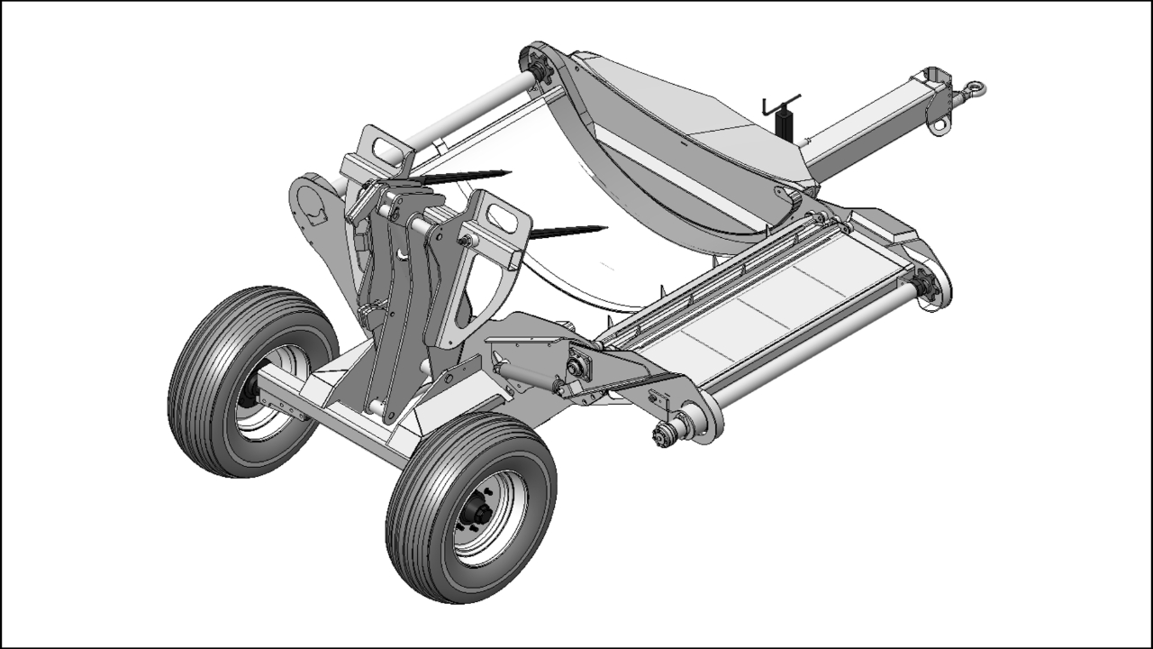
This is a Knowby on how to retrofit a DMLG2x2 extension.
1
Step 1 of 54
<p><span>Use the hydraulics to centralize a chain
joiner link in the cutout as shown.</span><br></p>

Use the hydraulics to centralize a chain joiner link in the cutout as shown.

2
Step 2 of 54
<p><span>Remove the joiner link nuts with a 24mm
socket.</span></p><p>DO NOT remove the joiner links!</p>

Remove the joiner link nuts with a 24mm socket.

DO NOT remove the joiner links!

3
Step 3 of 54
<p><span>While standing at the front of the unit,
reach under the string bin and pull out the front joiner link.</span><br></p>

While standing at the front of the unit, reach under the string bin and pull out the front joiner link.

4
Step 4 of 54
<p><span>While standing at the rear of the unit,
reach under the boom assembly and pull out the rear joiner link.</span><br></p>

While standing at the rear of the unit, reach under the boom assembly and pull out the rear joiner link.

5
Step 5 of 54
<p><span>Place a pallet on the ground under the
side of the DMLG2x2.</span><br></p>

Place a pallet on the ground under the side of the DMLG2x2.

6
Step 6 of 54
<p><span>Use the hydraulics to slowly run the
chain and bar assembly off the DMLG2x2 and onto the pallet.</span><br></p>

Use the hydraulics to slowly run the chain and bar assembly off the DMLG2x2 and onto the pallet.

7
Step 7 of 54
<p><span>Move the pallet of chains and bars out of
the way of the working area.</span><br></p>

Move the pallet of chains and bars out of the way of the working area.

8
Step 8 of 54
<p><span>Remove the two side covers as shown.</span><br></p>

Remove the two side covers as shown.

9
Step 9 of 54
<p><span>Place a drip tray underneath the
connections for the hydraulic motor to catch any oil spillage.</span><br></p>

Place a drip tray underneath the connections for the hydraulic motor to catch any oil spillage.

10
Step 10 of 54
<p><span>Remove the motor mount retaining bolt.</span><br></p>

Remove the motor mount retaining bolt.

11
Step 11 of 54
<p><span>Disconnect the hydraulic motor hoses as
shown.</span><br></p>

Disconnect the hydraulic motor hoses as shown.

12
Step 12 of 54
<p><span>Place caps over the Motor fittings &amp;
in the ends of the hydraulic hoses to keep debris out.</span><br></p>

Place caps over the Motor fittings & in the ends of the hydraulic hoses to keep debris out.

13
Step 13 of 54
<p><span>Rotate the motor &amp; mount by hand to
line up one of the grub screws with the gap in the shaft Guard &amp; then
loosen it.</span><br></p>

Rotate the motor & mount by hand to line up one of the grub screws with the gap in the shaft Guard & then loosen it.

14
Step 14 of 54
<p><span>While holding the motor in place, Use a
prybar to rotate the driveshaft until the second grub screw lines up with the
gap in the shaft Guard &amp; loosen it as well.</span><br></p>

While holding the motor in place, Use a prybar to rotate the driveshaft until the second grub screw lines up with the gap in the shaft Guard & loosen it as well.

15
Step 15 of 54
<p><span>Remove the motor and motor mount assembly
from the unit.</span><br></p>

Remove the motor and motor mount assembly from the unit.

16
Step 16 of 54
<p><span>Remove the hose clamp holding the motor
hoses as shown.</span><br></p>

Remove the hose clamp holding the motor hoses as shown.

17
Step 17 of 54
<p><span>Remove the 2 driveshaft adjuster bolts.</span><br></p>

Remove the 2 driveshaft adjuster bolts.

18
Step 18 of 54
<p><span>Remove the driveshaft assembly as shown.</span><br></p>

Remove the driveshaft assembly as shown.

19
Step 19 of 54
<p><span>Bolt the Rear mount &amp; Rear lower
guide to the unit as shown.</span></p><p><span><br></span></p><p>3x)
“B12x30” Bolts</p><p>4x)
“SC12x35ACS” Countersunk bolts</p><p>7x)
“NN12” Nylock nuts</p><p>1x) “14196” Rear mount</p><p>1x) “14193” Lower guide (Rear)</p>

Bolt the Rear mount & Rear lower guide to the unit as shown.


3x) “B12x30” Bolts

4x) “SC12x35ACS” Countersunk bolts

7x) “NN12” Nylock nuts

1x) “14196” Rear mount

1x) “14193” Lower guide (Rear)

20
Step 20 of 54
<p><span>Bolt the front mount &amp; Front lower
guide to the unit as shown.</span></p><p><span><br></span></p><p>3x)
“B12x35” Bolts</p><p>3x)
“SC12x45ACS” Countersunk bolts</p><p>6x)
“NN12” Nylock nuts</p><p>1x) “14195” Front mount</p><p>1x) “14193” Lower guide (Front)</p>

Bolt the front mount & Front lower guide to the unit as shown.


3x) “B12x35” Bolts

3x) “SC12x45ACS” Countersunk bolts

6x) “NN12” Nylock nuts

1x) “14195” Front mount

1x) “14193” Lower guide (Front)

21
Step 21 of 54
<p><span>Bolt the overolller to the DMLG2x2 as shown.</span></p><p><span><br></span></p><p>4x) “B12x35” Bolts</p><p>4x)
“NN12” Nylock nuts</p><p>1x)
“14192” Overroller</p>

Bolt the overolller to the DMLG2x2 as shown.


4x) “B12x35” Bolts

4x) “NN12” Nylock nuts

1x) “14192” Overroller

22
Step 22 of 54
<p><span>Bolt on both upper guides as shown.</span></p><p><span><br></span></p><p>4x) “B12x25” Bolts</p><p>4x) “NN12” Nylock nuts</p>

Bolt on both upper guides as shown.


4x) “B12x25” Bolts

4x) “NN12” Nylock nuts

23
Step 23 of 54
<p><span>Clean the two shaft stubs with emery
tape.</span><br></p>

Clean the two shaft stubs with emery tape.

24
Step 24 of 54
<p><span>Lift the extension into place over the
side of the DMLG2x2 as shown.</span><br></p>

Lift the extension into place over the side of the DMLG2x2 as shown.

25
Step 25 of 54
<p><span>Place the bearing bolts through the bolt
holes on the extension as shown.</span></p><p><span><br></span></p><p>4x) “B14x40” Bolts</p><p>4x) “B14x50” Bolts</p>

Place the bearing bolts through the bolt holes on the extension as shown.


4x) “B14x40” Bolts

4x) “B14x50” Bolts

26
Step 26 of 54
<p><span>Lower the extension down into position as
shown.</span><br></p>

Lower the extension down into position as shown.

27
Step 27 of 54
<p><span>Slide the bearings onto the shaft stubs
&amp; bolt them in place as shown.</span><br></p>

Slide the bearings onto the shaft stubs & bolt them in place as shown.

28
Step 28 of 54
<p><span>Make sure the extension is centered.</span><br></p>

Make sure the extension is centered.

29
Step 29 of 54
<p><span>Tighten the 4x bearing grub screws.</span><br></p>

Tighten the 4x bearing grub screws.

30
Step 30 of 54
<p><span>Attach the bottom end of the Ram to the
Ram mount as shown.</span></p><p><span><br></span></p><p>1x) “SP8x50” Split pin</p><p>1x) “11202” Stainless Washer</p>

Attach the bottom end of the Ram to the Ram mount as shown.


1x) “SP8x50” Split pin

1x) “11202” Stainless Washer

31
Step 31 of 54
<p><span>Remove the two plugs from the ram ports
and extend the ram by hand.</span><br></p>

Remove the two plugs from the ram ports and extend the ram by hand.

32
Step 32 of 54
<p><span>Bolt the head of the ram to the extension
by lining up the Ram mount and Ram eye with the access hole in the Rear lower
guide.</span></p><p><span><br></span></p><p>1x) “BF7/8X3-1/2” Imperial bolt</p><p>1x) “NNF7/8” Imperial nylock nut</p>

Bolt the head of the ram to the extension by lining up the Ram mount and Ram eye with the access hole in the Rear lower guide.


1x) “BF7/8X3-1/2” Imperial bolt

1x) “NNF7/8” Imperial nylock nut

33
Step 33 of 54
<p><span>Bolt the driveshaft assembly onto the
extension with the original bolts as shown.</span></p><p><span><br></span></p><p>2x) “B12x50” Bolts</p><p>2x) “WASG12” Spring washers</p><p>2x) “N12” Nuts</p>

Bolt the driveshaft assembly onto the extension with the original bolts as shown.


2x) “B12x50” Bolts

2x) “WASG12” Spring washers

2x) “N12” Nuts

34
Step 34 of 54
<p><span>Remove both the motor shaft grub screws
from the Motor
drive coupling and clean the threads with a tap.</span><br></p>

Remove both the motor shaft grub screws from the Motor drive coupling and clean the threads with a tap.

35
Step 35 of 54
<p><span>Make sure the key steel is still in the
motor shaft and slide it back into the driveshaft coupling.</span><br></p>

Make sure the key steel is still in the motor shaft and slide it back into the driveshaft coupling.

36
Step 36 of 54
<p><span>Rotate the motor assembly until one of
the grub screw pockets line up with the gap in the shaft Guard then reinsert
and tighten the first grub screw.</span><br></p>

Rotate the motor assembly until one of the grub screw pockets line up with the gap in the shaft Guard then reinsert and tighten the first grub screw.

37
Step 37 of 54
<p><span>Rotate the motor assembly until the
second grub screw pocket lines up with the gap in the shaft Guard then reinsert
and tighten the second grub screw.</span><br></p>

Rotate the motor assembly until the second grub screw pocket lines up with the gap in the shaft Guard then reinsert and tighten the second grub screw.

38
Step 38 of 54
<p><span>Secure the Motor mounting Bracket in
place with the original bolt.</span></p><p><span><br></span></p><p>1x) “605-3001-1” Floor Slat Bush</p><p>1x) “B12x50” Bolt</p><p>1x “NN12” Nylock nut</p>

Secure the Motor mounting Bracket in place with the original bolt.


1x) “605-3001-1” Floor Slat Bush

1x) “B12x50” Bolt

1x “NN12” Nylock nut

39
Step 39 of 54
<p><span>Remove the 3x hose clamps holding the
motor hoses.</span><br></p>

Remove the 3x hose clamps holding the motor hoses.

40
Step 40 of 54
<p><span>Feed the hydraulic hoses through the rear
passthrough and run them to the motor as shown.</span></p><p>Leave some slack between the motor and
the clamp.</p><p>Twist the hose clamp to keep the hoses
away from the bearing.</p><p><br></p><p>2x) Hose 9</p><p>1x) "CL16D" Complete hose clamp</p><p>1x) "M8x55" Bolt</p><p>1x) "NN8" Nylock nut</p>

Feed the hydraulic hoses through the rear passthrough and run them to the motor as shown.

Leave some slack between the motor and the clamp.

Twist the hose clamp to keep the hoses away from the bearing.


2x) Hose 9

1x) "CL16D" Complete hose clamp

1x) "M8x55" Bolt

1x) "NN8" Nylock nut

41
Step 41 of 54
<p><span>Screw two elbow fittings into the
hydraulic ram ports.</span></p><p>2x) “HYFA-A-90-0606” Elbow fittings.</p>

Screw two elbow fittings into the hydraulic ram ports.

2x) “HYFA-A-90-0606” Elbow fittings.

42
Step 42 of 54
<p><span>Pull the original motor hoses through to
the correct length and clamp all 4 hoses in place as shown.</span></p><p><span><br></span></p><p>1x) "CL16D" Complete hose clamp
+ extra blocks</p><p>1x) "M8x60" Bolt</p>

Pull the original motor hoses through to the correct length and clamp all 4 hoses in place as shown.


1x) "CL16D" Complete hose clamp + extra blocks

1x) "M8x60" Bolt

43
Step 43 of 54
<p><span>Attach the original motor hoses to the
ram as shown.</span><br></p>

Attach the original motor hoses to the ram as shown.

44
Step 44 of 54
<p><span>Feed the new Hydraulic hoses along the
path of the original motor hoses and through the string bin, then pull them out
to the same length as the original hoses.</span><br></p>

Feed the new Hydraulic hoses along the path of the original motor hoses and through the string bin, then pull them out to the same length as the original hoses.

45
Step 45 of 54
<p><span>Clamp the hoses in place under the bed
using hose clamps.</span></p><p><span><br></span></p><p>2x) "CL16D" Complete hose clamp
+ extra blocks</p><p>2x) "M8x60" Bolt</p>

Clamp the hoses in place under the bed using hose clamps.


2x) "CL16D" Complete hose clamp + extra blocks

2x) "M8x60" Bolt

46
Step 46 of 54
<p><span>Cabletie a “Tilt” tag to the hydraulic ram hoses
and a “Feed” tag to the motor hoses.</span></p><p><span><br></span></p><p>1x) “14813” Tilt tag</p><p>1x) “12558” Feed tag</p>

Cabletie a “Tilt” tag to the hydraulic ram hoses and a “Feed” tag to the motor hoses.


1x) “14813” Tilt tag

1x) “12558” Feed tag

47
Step 47 of 54
<p><span>Raise the extension using the Hydraulics.</span><br></p>

Raise the extension using the Hydraulics.

48
Step 48 of 54
<p><span>Move the chains under the extension, lift
them up and feed them into the drive sprocket.</span><br></p>

Move the chains under the extension, lift them up and feed them into the drive sprocket.

49
Step 49 of 54
<p><span>Feed the chains in
using the hydraulics.</span></p><p>Feed the chains around until they reach
the chain joining gap under the unit.</p>

Feed the chains in using the hydraulics.

Feed the chains around until they reach the chain joining gap under the unit.

50
Step 50 of 54
<p><span>Attach the chain extension to
the end of the original chain.</span><br></p>

Attach the chain extension to the end of the original chain.

51
Step 51 of 54
<p><span>Lift the extended chain up and feed it
down into the guide as shown.</span><br></p>

Lift the extended chain up and feed it down into the guide as shown.

52
Step 52 of 54
<p><span>Join the chain underneath using the bar
and joiner links from when you disconnected the chain.</span></p><p>If the bars either side of the join are
facing the same direction, install the joining bar facing the opposite
direction.</p><p><br></p><p>2x) “CH15000-3CONNECTOR” Chain joiners</p><p>1x) “127-0255” Spiked bar</p>

Join the chain underneath using the bar and joiner links from when you disconnected the chain.

If the bars either side of the join are facing the same direction, install the joining bar facing the opposite direction.


2x) “CH15000-3CONNECTOR” Chain joiners

1x) “127-0255” Spiked bar

53
Step 53 of 54
<p><span>Adjust the tensioners until the slack
under the unit is gone, but the chain is not tight.</span><br></p>

Adjust the tensioners until the slack under the unit is gone, but the chain is not tight.

54
Step 54 of 54
<p><span>Run up the unit making sure to test the
extension raising &amp; lowering and the chain rotation.</span><br></p>

Run up the unit making sure to test the extension raising & lowering and the chain rotation.