


Contents
Contents


Component list

Component list


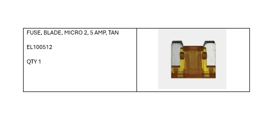

Components List

Tools Required

Tools Required

Loctite used throughout the canopy installation.
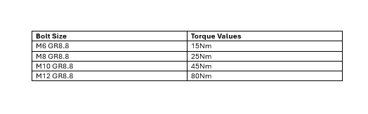
Torque Values

Disconnect the negative (–) terminal from the vehicle battery to isolate the electrical system.
Remove the plastic trim panels from the tub well-sides and tailgate

Carefully bend the tailgate flange on both sides to the required position.
Fit the tailgate bracket and secure it to the vehicle using the original screws removed earlier.
Where a tub liner is fitted, trim or modify it as required to allow fitment of the front corner brackets.
Apply 19 mm × 9 mm foam tape to the front edge of the tub well side. Apply urethane sealant along the edges to fill any gaps, ensuring all voids are fully sealed from top to bottom.
Ensure to use tape prep
Install the front mounting brackets to the tub well-sides. Secure each bracket (CP106735) using an M8 × 25 hex-head bolt and washer, applying Loctite to the threads.
Remove the rear tie-down points from the vehicle. Install the rear mounting brackets (CP106734) and refit the tie-down points, securing them loosely with M8 × 25 hex-head bolts and washers. Ensure Loctite is applied to the threads.

The left rear bracket will need to be cut where the mark is.
Fit the bracket to the spot shown.
Tighten the bracket to the wellside.

Install the D-TYPE rubber (RS106728) seal to each of the side rails as shown.
Ensure to use tape prep
Fit the side rails (CP106728/29) and front channel brackets onto the tub well-sides, ensuring correct alignment before securing
Attach the front-side mounting brackets (CP107794) and spacer brackets using M8 × 50 hex-head bolts. Apply Loctite to the threads, but leave all bolts loose to allow for easier canopy adjustment.
Attach the front channel (CP106727) to the front-side mounting brackets (CP106731/32) using M8 × 25 hex-head bolts, washers, and Nyloc nuts. Leave all fasteners loose to allow for canopy adjustment.
Apply urethane sealant to the corners of the fitting kit, ensuring all gaps are fully filled to create an effective seal between the canopy and the kit.

Apply tape primer to the bottom of the canopy to prepare the surface for foam tape adhesion.
Position 40 mm × 4.8 mm foam tape (RS109360) along the bottom of the canopy. Use additional foam tape in the corners for enhanced sealing, and place protective padding underneath the canopy to avoid scratches while fitting.
With a minimum of four people, carefully lift the canopy onto the fitting kit.
Adjust the canopy position so that the mounting holes on the canopy line up precisely with the holes on the fitting kit.
Secure the canopy to the tub well-sides using M8 × 50 hex-head bolts and M8 washers in the threaded mounting points. Apply Loctite to all fasteners. Take care not to scratch the canopy while tightening, and have a second person assist by supporting or gently pulling the canopy as required.
Ensure to use tape on the flange where you are tightening to prevent scratches.
Secure the canopy to the fitting kit at the front holes using M8 × 25 hex-head bolts and Nyloc nuts.
Position the rear reinforcing brackets (CP107139/40) on top of the canopy. Secure them to the rear upright brackets using M8 × 25 hex-head bolts, washers, and Nyloc nuts.

Fit the rear canopy bracket so that it sits over the top of the canopy side rail, ensuring correct alignment as illustrated.
Using the top hole of the reinforcing bracket, drill as required and fasten the bracket with an M8 × 25 hex-head bolt, washer, and Nyloc nut, ensuring proper alignment before tightening.

Check that the canopy is correctly aligned. The outer edges of the doors should run parallel with the angle of the rear uprights.
Once the fitting kit and canopy are in place, ensure the canopy is square and correctly aligned. Then tighten all fitting kit and mounting bolts to securely fix the canopy.
Apply the 16 mm × 9 mm D-type rubber (RS102633) to the tailgate bracket to create a seal between the canopy door and the fitting kit.
Run the cab to canopy loom on the driver's side of the wellside.
Pull the wiring loom out from under the tub well-side, ensuring it is fully accessible beneath the vehicle.
Remove the interior trim covering the A-pillar to allow access for canopy wiring.
Pass the cab-to-canopy wiring loom through the grommet beneath the driver’s seat. Modify the rubber grommet by creating a small opening so the loom can be routed without damage.
Pull the cab-to-canopy loom through the grommet and into the vehicle’s cab.
Identify the vehicle’s main plug. Connect the supplied in-cab wiring loom to the appropriate wires on this plug, following the correct color coding
Locate the grey wire with a brown stripe (Unlock) and the green wire with an orange stripe (Lock).
Carefully expose 10 mm of bare wire on each cable, taking care not to damage the conductor.

Strip 5-10mm from the 2 wires and split the pure white wire.
Connect the green cable to the grey with brown stripe.
Connect the Brown wire to the green wire with a orange stripe.
Ensure to solder the exposed wire correctly.
Carefully strip 10 mm of insulation from both ends to prepare for connection to the Door Ajar Alarm circuit.
Insert each stripped end of the wire into the T-joint on the in-cab loom.
Insulate the exposed wires with electrical tape, ensuring each wire is wrapped individually.

Connect the cab-to-canopy loom to the in-cab wiring loom as follows: white to white, red to orange, and black to black. Additional wires are provided for optional accessories.
Connect the in-cab wiring loom to the cab-to-canopy loom. Check the wiring instruction on page 50.
Remove the fuse from slot 29 and place it into the fuseblade holder. Then, insert the fuseblade holder back into slot 29 of the fusebox.
Connect the earth (black) wire from the in-cab loom to an existing factory earth point on the vehicle.

Remove screws from the latch.
Test all doors and rear lights to confirm they operate correctly.
Verify that the door alarm indicator illuminates when a canopy door is open.
Check that the canopy doors respond properly to the vehicle remote, locking and unlocking as intended.
Neatly secure all wiring and refit the interior trim panels.

Please fill out the hard copy QA sheet included with the product you got.Once filled out, please send back to
If the hard copy does not arrive, please contact us
0800 663 500