


Contents (Click to view)

Components List

Components List

Components List

Tools List
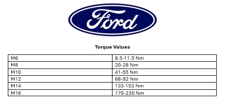
Torque Values

Clamp the L-angled alloy to the wellside.
Ensure it leaves room for the false floor to slide in between the RED ARROW.
Drill through the holes on the L-angle alloy and the wellside
Tighten the alloy to the wellside using an M8 x 30 button head bolts with M8 heavy washer and M8 nyloc nut.
Lift the false floor into the rear of the UTE.
Clamp the L-angle alloy to the bottom of the false floor. Drill holes to fit M6 CSK bolts in
Tighten using M6 Nyloc nut below
Slide the false floor to the front of the wellside.
Make a mark on the wellside through this hole.
Drill an 8.5mm hole through the mark on the wellside.
Insert a plus nut into the hole.
Using an M8 Hex head bolt to tighten the false floor to the front of the wellside.
Drill a pilot hole through the ply and alloy below with an 4mm drill bit.
Screw the false floor to the alloy using CSK tec screws. 2x each side.
Ply fitted to alloy.
Fit smaller angled alloy to the side of the wellside using CSK tec screws.
Fit J-bar to the rear of the false floor.
Once finished, ensure it is neat and tidy.

Please fill out the hard copy QA sheet included with the product you got.
Once filled out, please send it back to
If the hard copy does not arrive, please contact us.
0800 663 500