
Knowby
Ford Ranger 2022+ Load-Lid Fitting Instructions
1
Step 1 of 24
<p>Review dispatch list and confirm you have all the correct parts</p>

Review dispatch list and confirm you have all the correct parts

2
Step 2 of 24
<p>Remove the clips along the side of the plastic caps.</p><p>Repeat for both sides.</p>

Remove the clips along the side of the plastic caps.

Repeat for both sides.

3
Step 3 of 24
<p>Remove the plastic caps along the sides of the wellside.</p><p>The clips need to have at least one side pushed inwards to release the clip (A). Some clips need a prying tool (B) inserted under the outside of the caps to release the clips, particularly in the front and rear corners. However, most of the clips holding the caps in place can be accessed from inside the wellside using pliers (C).</p><p>Take care not to damage the clips or the caps, these will be re-installed later.</p><p>Repeat for both sides.</p>

Remove the plastic caps along the sides of the wellside.

The clips need to have at least one side pushed inwards to release the clip (A). Some clips need a prying tool (B) inserted under the outside of the caps to release the clips, particularly in the front and rear corners. However, most of the clips holding the caps in place can be accessed from inside the wellside using pliers (C).

Take care not to damage the clips or the caps, these will be re-installed later.

Repeat for both sides.

4
Step 4 of 24
<p>Run the provided sponge seal around the outside of the wellside in a continuous seal, starting at the tailgate on one side and ending at the tailgate on the other side.</p><p>Use the raised section (D) along the sides as a guide — the sponge seal should touch the raised section (E). In the front corners, the sponge seal should turn the corner and run along the front of the wellside (F).</p><p>Ensure the sponge seal is in front of the threads (G). Discard any surplus sponge seal.</p>

Run the provided sponge seal around the outside of the wellside in a continuous seal, starting at the tailgate on one side and ending at the tailgate on the other side.

Use the raised section (D) along the sides as a guide — the sponge seal should touch the raised section (E). In the front corners, the sponge seal should turn the corner and run along the front of the wellside (F).

Ensure the sponge seal is in front of the threads (G). Discard any surplus sponge seal.

5
Step 5 of 24
<p>Return the plastic caps to their original position, these should clip back in place.</p><p>The caps should compress the sponge seal, but ensure it doesn’t bulge out underneath the caps.</p><p>Also return the clips to their original position (see Step 1).</p><p>Repeat for both sides.</p>

Return the plastic caps to their original position, these should clip back in place.

The caps should compress the sponge seal, but ensure it doesn’t bulge out underneath the caps.

Also return the clips to their original position (see Step 1).

Repeat for both sides.

6
Step 6 of 24
<p>Remove the front clip (H) and bolt (I) holding the liner in the front corner.</p><p>Also remove the hooks from the front corner (J).</p><p>Repeat for both sides.</p>

Remove the front clip (H) and bolt (I) holding the liner in the front corner.

Also remove the hooks from the front corner (J).

Repeat for both sides.

7
Step 7 of 24
<p>Install the front infill bracket PRT-005957 to the front wall of the wellside, between the two plastic caps.</p><p>The overhang sits over the front wall and hangs down between the cab and the wellside (N).</p><p>Take care not to scratch the cab when installing. Ensure the foam compress tightly and leave no gaps.</p>

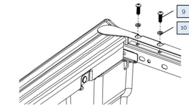
Install the front infill bracket PRT-005957 to the front wall of the wellside, between the two plastic caps.

The overhang sits over the front wall and hangs down between the cab and the wellside (N).

Take care not to scratch the cab when installing. Ensure the foam compress tightly and leave no gaps.
8
Step 8 of 24
<p>Bolt the infill bracket in place using the following fasteners:</p><ol start="9"><li><p>M8 x 25mm Btn Bolt</p></li><li><p>M8 Spring Washer</p></li></ol><p>Repeat for both sides.</p>

Bolt the infill bracket in place using the following fasteners:

  1. M8 x 25mm Btn Bolt

  2. M8 Spring Washer

Repeat for both sides.

9
Step 9 of 24
<p>If your Ranger has a spray liner, Click Here:&nbsp;</p><p>If it has a plastic liner, follow the instructions below:</p><p>Pull the front corner of the liner away from the wellside wall to give access behind. Insert the provided rubber gasket. This should sit inside the plastic cap (K). Bolt in place to the front thread using the following fasteners:<br>9) M8 x 25mm Btn Bolt</p><ol><li><p>M8 Spring Washer</p></li><li><p>M8 Medium Washer</p></li></ol><p>Do not overtighten, or the bolt head will pull through the rubber.</p><p>Return the liner to its original position, sitting over top of the rubber gasket. Return bolt (L) to its thread — this should pass through the hole in the rubber gasket. Re-insert the plastic liner clip (M).</p><p>Repeat for both sides.</p>

If your Ranger has a spray liner, Click Here: 

If it has a plastic liner, follow the instructions below:

Pull the front corner of the liner away from the wellside wall to give access behind. Insert the provided rubber gasket. This should sit inside the plastic cap (K). Bolt in place to the front thread using the following fasteners:
9) M8 x 25mm Btn Bolt

  1. M8 Spring Washer

  2. M8 Medium Washer

Do not overtighten, or the bolt head will pull through the rubber.

Return the liner to its original position, sitting over top of the rubber gasket. Return bolt (L) to its thread — this should pass through the hole in the rubber gasket. Re-insert the plastic liner clip (M).

Repeat for both sides.

10
Step 10 of 24
<p>Install PRT-005963 onto the front wall to cover up the open slotted holes.</p><p>Ensure the hole in the foam gasket lines up with the thread in the front wall, and that it covers both slotted holes.</p><p>Repeat for both sides.</p>

Install PRT-005963 onto the front wall to cover up the open slotted holes.

Ensure the hole in the foam gasket lines up with the thread in the front wall, and that it covers both slotted holes.

Repeat for both sides.

11
Step 11 of 24
<p>Install the front mounting brackets PRT-005962 into the front corners.</p><p>Re-install the hook and bolts through the brackets, leave loose at this stage.</p><p>Repeat for both sides.</p>

Install the front mounting brackets PRT-005962 into the front corners.

Re-install the hook and bolts through the brackets, leave loose at this stage.

Repeat for both sides.

12
Step 12 of 24
<p>Bolt into the front wall thread using the following fasteners:<br>9) M8 x 25mm Btn Bolt</p><p>10) M8 Spring Washer</p><p>11) M8 Medium Washer</p><p>Tighten these bolts and the hook bolts (from previous step).</p><p>Repeat for opposite side.</p>

Bolt into the front wall thread using the following fasteners:
9) M8 x 25mm Btn Bolt

10) M8 Spring Washer

11) M8 Medium Washer

Tighten these bolts and the hook bolts (from previous step).

Repeat for opposite side.

13
Step 13 of 24
<p>Remove the existing bolt in the top rear corner of the wellside (O).</p><p>Keep this bolt for using later.</p><p>Repeat for opposite side.</p><p>Note: If your Ranger doesn't have this bolt, you can skip this step.</p>

Remove the existing bolt in the top rear corner of the wellside (O).

Keep this bolt for using later.

Repeat for opposite side.

Note: If your Ranger doesn't have this bolt, you can skip this step.

14
Step 14 of 24
<p>Remove the hooks from the rear corners (P).</p><p>Repeat for opposite side.</p>

Remove the hooks from the rear corners (P).

Repeat for opposite side.

15
Step 15 of 24
<p>Install the rear mounting brackets PRT-005465-A into the rear corners.</p><p>Bolt in place using the original hook and bolts (Q) from the previous step.</p><p>Repeat for opposite side.</p>

Install the rear mounting brackets PRT-005465-A into the rear corners.

Bolt in place using the original hook and bolts (Q) from the previous step.

Repeat for opposite side.

16
Step 16 of 24
<p>Insert cardboard (R) between the cab and wellside to protect the paint from scratching during installation.</p><p>Note: Cardboard not supplied.</p>

Insert cardboard (R) between the cab and wellside to protect the paint from scratching during installation.

Note: Cardboard not supplied.

17
Step 17 of 24
<p>Lift the Load-Lid onto the vehicle.</p><p>Note: Lower the tailgate before lifting the Load-Lid into place. This will help with upcoming steps.</p>

Lift the Load-Lid onto the vehicle.

Note: Lower the tailgate before lifting the Load-Lid into place. This will help with upcoming steps.

18
Step 18 of 24
<p>Adjust the position of the Load-Lid forwards or backwards until the tension on the front rubber flap is correct.</p><p>See diagrams for more information.</p><p>Once the Load-Lid is sitting correctly, check it is sitting square on the wellside, not at an angle.</p>

Adjust the position of the Load-Lid forwards or backwards until the tension on the front rubber flap is correct.

See diagrams for more information.

Once the Load-Lid is sitting correctly, check it is sitting square on the wellside, not at an angle.

19
Step 19 of 24
<p>Without moving the Load-Lid, reach in through the open tailgate and insert the original bolt from Step 12 (S) through the mounting frame into the wellside thread.</p><p>Repeat for opposite side.</p><p>Note: If there was no bolt removed in Step 12, use:&nbsp;M6 x 20mm Btn Bolt</p>

Without moving the Load-Lid, reach in through the open tailgate and insert the original bolt from Step 12 (S) through the mounting frame into the wellside thread.

Repeat for opposite side.

Note: If there was no bolt removed in Step 12, use: M6 x 20mm Btn Bolt

20
Step 20 of 24
<p>Reach through the open tailgate and bolt through the mounting frame into the rear mounting bracket using the following fasteners:<br>8) M8 x 25mm Tri-Knob</p><p>10) M8 Spring Washer</p><p>12) M8 Fender Washer</p><p>Repeat for opposite side.</p>

Reach through the open tailgate and bolt through the mounting frame into the rear mounting bracket using the following fasteners:
8) M8 x 25mm Tri-Knob

10) M8 Spring Washer

12) M8 Fender Washer

Repeat for opposite side.

21
Step 21 of 24
<p>With someone holding the Load-Lid open for you.</p><p>Cut the cable ties holding the gas stays underneath the Load-Lid, and clip them into the brackets on the mounting frame.</p><p>The Load-Lid will support itself once both gas stays are connected.</p>

With someone holding the Load-Lid open for you.

Cut the cable ties holding the gas stays underneath the Load-Lid, and clip them into the brackets on the mounting frame.

The Load-Lid will support itself once both gas stays are connected.

22
Step 22 of 24
<p>In the front corners, bolt through the mounting frame and front mounting bracket into the provided thread plate, using the following fasteners:<br>8) M8 x 25mm Tri-Knob</p><p>10) M8 Spring Washer</p><p>12) M8 Fender Washer</p><p>4) PRT-005964</p><p>Note: The thread plate sits underneath the front mounting bracket.</p><p>Fully tighten the fasteners.</p><p>Repeat for opposite side.</p>

In the front corners, bolt through the mounting frame and front mounting bracket into the provided thread plate, using the following fasteners:
8) M8 x 25mm Tri-Knob

10) M8 Spring Washer

12) M8 Fender Washer

4) PRT-005964

Note: The thread plate sits underneath the front mounting bracket.

Fully tighten the fasteners.

Repeat for opposite side.

23
Step 23 of 24
<p>Adjust the nuts on the lock strike to affect the final closing height of the Load-Lid.</p><p>Click this link to watch a video on how to adjust the latches:&nbsp;</p>

Adjust the nuts on the lock strike to affect the final closing height of the Load-Lid.

Click this link to watch a video on how to adjust the latches: 

24
Step 24 of 24

IMPORTANT NOTE:

  • When removing and refitting:
    Disconnect the gas stays and lock the Load-Lid into the mounting frame before undoing the clamps and removing the Load-Lid (this prevents damaging the wellside).

  • When refitting the Load-Lid, ensure the rubber flap at the front of the Load-Lid is pressing firmly against the front of the wellside (refer to Step 17).

  • If your Load-Lid has a rattle when driving, loosen all clamps and pull the Load-Lid back slightly to ensure the rubber flap is pressing firmly on the front (refer to Step 17), and re-tighten all clamps.