Knowby Landquip Ltd
Knowby
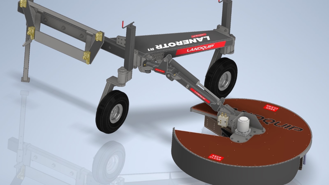
LaneRotr R1 assembly
Assembly process
Assembly process
1
Step 1 of 23
<p>Ensure toolboard is 100% ready to go, all tools are there, bolt kit, hose kit, plastic guard top, Chevron rubber, decal kit, bearings, wear pads, bearing covers, valves x2, strap, rubber pads, are all complete and in place. Floor is swept and tidy. Assy stand and assy table are in place ready to go.</p>

Ensure toolboard is 100% ready to go, all tools are there, bolt kit, hose kit, plastic guard top, Chevron rubber, decal kit, bearings, wear pads, bearing covers, valves x2, strap, rubber pads, are all complete and in place. Floor is swept and tidy. Assy stand and assy table are in place ready to go.

2
Step 2 of 23
<p>Place a STRONG pallet on table and lay sheet of bubble wrap.</p>

Place a STRONG pallet on table and lay sheet of bubble wrap.

3
Step 3 of 23
<p>Bring in all painted sections, place tidy on a pallet out of the way for both assy stations.</p>

Bring in all painted sections, place tidy on a pallet out of the way for both assy stations.

4
Step 4 of 23
<p>Grease bearings/hubs using grease cone and battery grease gun, assemble hubs.</p>

Grease bearings/hubs using grease cone and battery grease gun, assemble hubs.

5
Step 5 of 23
<p>Assemble this section on stand, remove tape from both shafts.</p>

Assemble this section on stand, remove tape from both shafts.

6
Step 6 of 23
<p>Fit greased hub sets to wheel stubs, and bolt on wheels.</p>

Fit greased hub sets to wheel stubs, and bolt on wheels.

7
Step 7 of 23
<p>Assemble this wind jack section</p>

Assemble this wind jack section

8
Step 8 of 23
<p>Assemble the 2 wheel assemblies together on stand. Put aside 2 complete wheel assemblys.</p>

Assemble the 2 wheel assemblies together on stand. Put aside 2 complete wheel assemblys.

9
Step 9 of 23
<p>Assemble knuckle assembly using jig stand, fit bushes and grease nipples</p>

Assemble knuckle assembly using jig stand, fit bushes and grease nipples

10
Step 10 of 23
<p>Remove tape from pivot pins</p>

Remove tape from pivot pins

11
Step 11 of 23
<p>Lay main chassis section onto pallet in correct position (photo incorrect position)</p>

Lay main chassis section onto pallet in correct position (photo incorrect position)

12
Step 12 of 23
<p>Hoist up hitch frame and bolt onto main chassis</p>

Hoist up hitch frame and bolt onto main chassis

13
Step 13 of 23
<p>Have pivot clevis hanging off the pallet so top and bottom holes can be die-ground out for pin to fit if needed.</p>

Have pivot clevis hanging off the pallet so top and bottom holes can be die-ground out for pin to fit if needed.

14
Step 14 of 23
<p>Position the chassis on the pallet with the main beam parallel with the pallet edge, and the pivot clevis about 200mm in from the pallets 'strong' edge like photo.</p>

Position the chassis on the pallet with the main beam parallel with the pallet edge, and the pivot clevis about 200mm in from the pallets 'strong' edge like photo.

15
Step 15 of 23

Fit breakaway bracket

16
Step 16 of 23

Fit knuckle to arm clevis

17
Step 17 of 23

Bolt breakaway system together

18
Step 18 of 23

Prop knuckle box section onto piece of wood and strap down to trolly using 3 straps.

19
Step 19 of 23

Fit arm and ram to knuckle

20
Step 20 of 23

Fit adjustment bracket to arm and cross port relief valve.

21
Step 21 of 23

Fit motor mount bracket to adjustment bracket.

22
Step 22 of 23

Fit the bolt-on loop and hold it with hoist while fitting the motor to the motor-mount bracket.

23
Step 23 of 23

Hose up all hydraulics from the hose kit.