
Knowby
WideTrac - Replace Drive Assembly
This Knowby will run you through step by step on how to Replace WideTrac Drive Assembly
1
Step 1 of 38
<p>Using the controller, menu option 4: Test Gate, raise door to fully open position</p>

Using the controller, menu option 4: Test Gate, raise door to fully open position

2
Step 2 of 38
<p>Connect and engage hydraulics. Wind in manual override knob on valve to run belt until belt join is between impact guard profiles. If no manual override fitted to valve, use &quot;Test Belt&quot; option in controller</p>

Connect and engage hydraulics. Wind in manual override knob on valve to run belt until belt join is between impact guard profiles. If no manual override fitted to valve, use "Test Belt" option in controller

3
Step 3 of 38
<p>Fully unwind belt tensioners</p>

Fully unwind belt tensioners

4
Step 4 of 38
<p>Remove 2 tractor hoses from rear of valve and the floor drive cable.</p>

Remove 2 tractor hoses from rear of valve and the floor drive cable.

5
Step 5 of 38
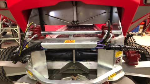
<p>Disconnect 2 hoses from floor gearbox motor</p>

Disconnect 2 hoses from floor gearbox motor

6
Step 6 of 38
<p>Remove spinner sensor and take out of loom</p>

Remove spinner sensor and take out of loom

7
Step 7 of 38
<p>Support weight of spinner frame and remove spinner frame mounting bolts and stainless deflector bolts from both sides</p>

Support weight of spinner frame and remove spinner frame mounting bolts and stainless deflector bolts from both sides

8
Step 8 of 38

Remove spinner frame from machine

9
Step 9 of 38
<p>Remove belt joiner cable. Remove washer from one end of cable and pull through opposite end</p>

Remove belt joiner cable. Remove washer from one end of cable and pull through opposite end

10
Step 10 of 38
<p>Remove chain joiner links and split belt</p>

Remove chain joiner links and split belt

11
Step 11 of 38

Pull top section of chain up and over drive sprockets and hold up and out off drive sprockets. Seal strips may need to be unscrewed from plastic bin to allow easier access

12
Step 12 of 38
<p>Support drive assembly frame and remove 2 bolts from brass support bushing</p>

Support drive assembly frame and remove 2 bolts from brass support bushing

13
Step 13 of 38
<p>Remove grease lines from bearings</p>

Remove grease lines from bearings

14
Step 14 of 38
<p>Remove gearbox torque arm bolts</p>

Remove gearbox torque arm bolts

15
Step 15 of 38
<p>Disconnect gearbox motor speed sensor</p>

Disconnect gearbox motor speed sensor

16
Step 16 of 38
<p>Remove drive assembly from machine. Complete with gearbox and motor</p>

Remove drive assembly from machine. Complete with gearbox and motor

17
Step 17 of 38
<p>Remove LH sprocket and key (Furthest from driveshaft) from shaft</p>

Remove LH sprocket and key (Furthest from driveshaft) from shaft

18
Step 18 of 38
<p>Remove gearbox, shaft and sprocket from drive assembly</p>

Remove gearbox, shaft and sprocket from drive assembly

19
Step 19 of 38
<p>Refit gearbox, shaft and sprocket into new drive assembly</p>

Refit gearbox, shaft and sprocket into new drive assembly

20
Step 20 of 38
<p>Fit key and sprocket onto shaft and fasten grub screw. Sprocket centres should be 819mm +/-2mm</p>

Fit key and sprocket onto shaft and fasten grub screw. Sprocket centres should be 819mm +/-2mm

21
Step 21 of 38
<p>Fit new drive assembly on machine</p>

Fit new drive assembly on machine

22
Step 22 of 38
<p>Fasten brass bearing</p>

Fasten brass bearing

23
Step 23 of 38
<p>Fit new grease lines and grease bearings</p>

Fit new grease lines and grease bearings

24
Step 24 of 38
<p>Fasten gearbox torque arm and fit gearbox motor speed sensor</p>

Fasten gearbox torque arm and fit gearbox motor speed sensor

25
Step 25 of 38
<p>Check slats on either side of joiner. If not riveted, lay slat in position and use as jig for drilling hole through belt. DO NOT RIVET UNTIL BELT IS JOINED.</p>

Check slats on either side of joiner. If not riveted, lay slat in position and use as jig for drilling hole through belt. DO NOT RIVET UNTIL BELT IS JOINED.

26
Step 26 of 38
<p>Pull belt back out of machine and join chain using joiner links.</p>

Pull belt back out of machine and join chain using joiner links.

27
Step 27 of 38

Use 5mm round bar to align belt joiner

28
Step 28 of 38

Push joiner wire through while pulling the 5mm align bar out.

29
Step 29 of 38
<p>Fit and bend washer on end of wire to retain</p>

Fit and bend washer on end of wire to retain

30
Step 30 of 38

Fit and bend washer on end of wire to retain

31
Step 31 of 38

Evenly tension chain and belt until there is ~75mm of movement in the chain

32
Step 32 of 38
<p>Lock tensioners</p>

Lock tensioners

33
Step 33 of 38

If no rivets fitted to slats either side of joiner, fit rivets now.

34
Step 34 of 38
<p>Refit spinner frame and tighten mounting bolts</p>

Refit spinner frame and tighten mounting bolts

35
Step 35 of 38
<p>Fit tractor hoses to valve and the floor drive cable.</p>

Fit tractor hoses to valve and the floor drive cable.

36
Step 36 of 38
<p>Fit hoses to gearbox motor</p>

Fit hoses to gearbox motor

37
Step 37 of 38
<p>Fit spinner sensor</p>

Fit spinner sensor

38
Step 38 of 38
<p>Check operation of belt using the manual override knob on the valve.
Wind knob as far out as possible once completed. If no manual override knob fitted, use &quot;Test Gate&quot; option on controller</p>

Check operation of belt using the manual override knob on the valve. Wind knob as far out as possible once completed. If no manual override knob fitted, use "Test Gate" option on controller