The information covered in this instruction applies to machines with either 300 or 1000 PSI systems built between November 2013 and July 2015.
We'll show how to check if the system is functioning correctly and then steps you through the process of replacing the ACF filter bag.
To start, check if there's an issue with the coolant pressure.
Since the ACF unit is most commonly used on TSC systems, let's see how that system behaves when there's a clogged ACF filter.
Activate TSC with the spindle turning slowly.
Before checking the auxiliary coolant tank, first check that the coolant level readout on the screen shows that the tank is full.
And just to make sure someone hasn't left the coolant level sensor out of the tank, visually check that there's sufficient coolant in the tank.
Yes, the tank is full.
Now activate the coolant system again to pressurize the auxiliary coolant filter tank.
Return to the back of the machine to check the filter gauge on the ACF tank. This will tell you whether the system is flowing freely or if it's plugged up.
The ACF tank needs to be drained, so start by disconnecting the supply line at the pump site and direct the stream of coolant into the chip tray.
This drains the coolant in the ACF back into the main coolant tank.
Next, open the four latches that secure the lid to the tank.
Remove the lid.
Wait for the tank to drain.
This usually takes about 5 minutes.
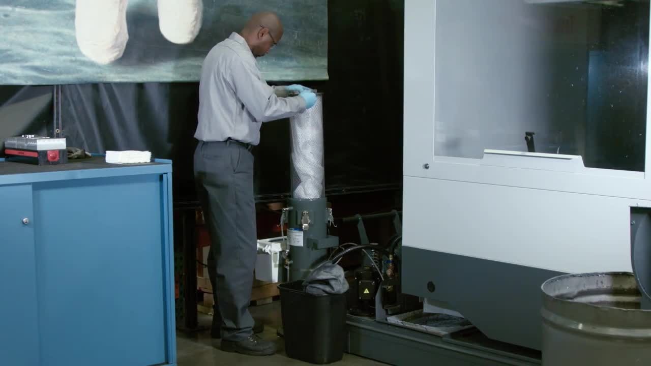
Remove the metal strainer and the filter bag assembly.
Place the strainer into a plastic waste can while removing the filter bag.
Then install a new filter bag into the metal strainer.
Push the bag into the recessed area below the strainer's top edge.
Place the metal strainer and the filter bag back into the tank.
Before reinstalling the lid, apply a thin layer of general purpose grease to the seal on the lid.
Then install the lid on the tank and make sure to match the alignment marks on the tank and the lid.
Then attach the four latches.
Clamping each set of opposite latches at the same time will keep the lid from caulking.
Reconnect the supply line to the coolant pump and wipe away any spilled coolant.
Run the standard coolant pump for about 5 minutes or until you see the tank is full.
Don't activate TSC until the tank is filled.
With the tank full, activate the TSC system and check that the tank lid and other connection points are leak free.
Once this checks out, the procedure is complete.
For more information, check this manual.