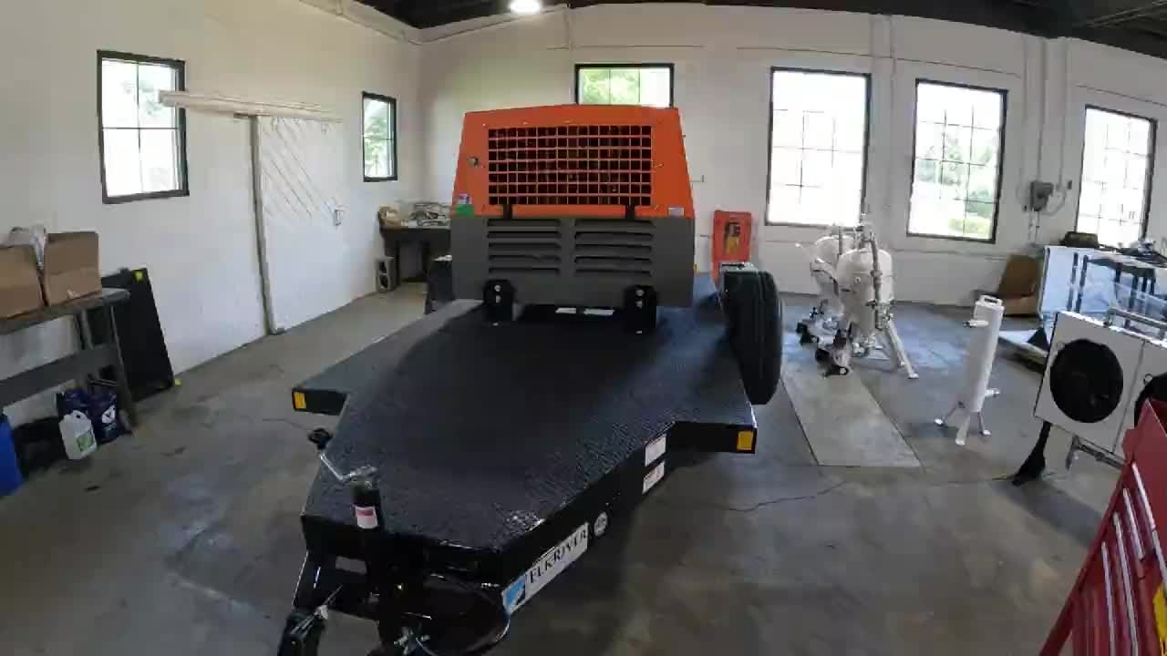
Watch our fabricator perform a final assembly for a trailer system
Okay, first, we're going to go up here, cut the zip tie on our exhaust.
We're going to then remove these wing nuts and fold this down so we have access to the engine.
We're going to take this duct tape cover off here.
We're going to open this panel up and get the box out that has a three-way valve.
And then we're going to set our three pieces of equipment up here on the deck.
So, we're going to take this one.
One, two, three, four, five, six, seven holes for the pot. There's three pre-drilled holes for the moisture separator.
The fan, we drill the holes after. Okay, next, we're going to run our plumbing from the opening coming out of the compressor to the valve down and across.
I've got two pre-built assemblies here. My first one is going to come out of the machine.
Here's my valve. It's got a one-inch stainless elbow to a one-inch close nipple to a one-inch ball valve to a 30-inch by one-inch stainless custom pipe down to one more elbow.
And then I've got my 47-inch for across the bottom to my one-inch elbow.
All taped up. These are all completed. And there's my one-inch close nipple that's going to come out and go into it.
We put three wraps of tape on every fitting.
And then we dope every fitting.
So I've got that started.
Now I'm going to install the 30" pipe with the ball valve into the exit port from the compressor.
There are four bolts here that can be loosened up to make this exit pipe move up and down or back and forth about a quarter of an inch if you need it.
Sometimes it's too high up off the trailer. Sometimes it's too close to the trailer and you can't spin it.
This one seems pretty good though.
So I'm going to leave it back, talk back a little bit so that we can put our next one in.
Just going to take it one to the bottom.
Now we will install the 47" pipe with elbow across the bottom.
And then spin it. So it's tight. And it's coming straight up.
And then we're going to run a hose. Down from here.
I've got to complete my connection. From the elbow at the top of the fans.
Down to that elbow coming out. I'm going to use.
I've got it taped up at this end. The male end is going to go into the top.
And then at the bottom. I've got a spinning union.
And we're going to connect it to this. With a 2 and a quarter inch long nipple.
Okay now that we've got our equipment set up on the trailer.
We're going to mount the blast pot. And the moisture separator to the trailer bed.
I've got two half inch bolts for the legs on the blast pot
With lock nuts. And washers. Those are going to go in the two legs of the pot.
Over here. And then I've got seven 7/16" bolts.
Washers and lock nuts. Those are going to go in the three legs of the.
Moisture separator. And over here. On the mounts of the blast pot. Two on each side. So one washer.
On the top. The nut goes through. And then. We'll put the other washer. And the lock nut on the bottom.
I will tighten them as much as I can get them with my hand I'm not going to tighten these up until after my plumbing is done so as long as I put the nut on it'll hold it in place so they can't move.
That way our equipment is set in place, can't move but we can move it enough just to get our plumbing tightened up when we plumb these all together.
Okay, now I'm going to run my plumbing from the top air outlet of the moisture separator down into the inlet elbow on the blast pot.
I've got two sub-assemblies here ready to go. This is going to come off of the moisture separator.
This has a one inch stainless elbow, a 12 inch nipple with part of my union that I've got tape.
Then the other fitting is my other half of my union. I've got a three and a half inch nipple, an elbow, a two and a half inch nipple, a T and a six inch flex hose.
We're going to install both of those.
put the union together as long as it fits. Sometimes because of the nature of the legs on the moisture separator and the pot and the holes put in the trailer, sometimes some of these nipples will have to be changed out to other sizes.
And then once we get everything mounted, then we will put our three wave valve in here. So, we're going to have to do a second.
So, now we are plumbed from the blast pot up to the moisture separator.
Next, we're going to put this three-way valve that comes with the Sullivan Palatek compressor.
We're going to mount it in here with a closed nipple here. And then, we're going to put a couple of three-quarter inch female Chicago fittings on here.
Okay. We've got our auxiliary foot valve with our Chicago fittings all connected, ready to go.
Okay. Next, we're going to plumb from the bottom of the moisture separator over to the fan.
We've got two sub-assemblies here. One is a six-inch flex hose with half of our union.
The other one is two 45-degree elbows with a three-and-a-half-inch nipple in between, a close nipple, and then the other half of our coupler.
And also, one close nipple that's going to go in here.
We're going to take a couple of minutes.
Now we're from our fan up to our moisture separator.
Okay. Next, we are going to drill holes and mount our fan feet to the trailer deck.
We're going to do four holes, four bolts. There are 7/16th bolts with a 7/16th lock nut & washer on both sides.
Lock nut goes on the bottom. We're drilling with a half inch drill bit.
These on the inside, we're going to use the hole that already exists.
On the outside, too, that run along the edge of the trailer, we can't use this hole because our support beam runs here underneath.
So we've got to go in a little bit further. We're going to go about three inches in from the edge of the trailer and drill a fresh hole here and here. This is to avoid the 2" rail on the perimeter of the trailer.
Clean this area up and place the bolt and washer thru each of the 4 holes.
The first thing is a 5/8 impact socket except for the two on the legs of the blast pot.
Those are 3/4 inch. It's a lot easier with two people if you have one person underneath and one person on top.
You can get them done a lot quicker. I've got to do one at a time though. Okay, next we're going to put two U-bolts on this pipe to hold this one moving around.
We're going to run one in line with these bolts, these mount bolts here and over there and then one on the other side.
We're going to go six inches over and six inches in and drill a hole here and here and over here and here.
U-bolts. They come with the nuts and this flat bar.
We're not going to use the flat. We're going to use washers because we're straddling a support underneath there.
We're straddling it so we can't use this. We're going to use washers and then we're going to use those nuts and we're going to also chase them with a 5/16 lock nut.
We're going to drill holes with a 3/8 drill bolt so it's got a little bit of slack.
Okay, we've got the holes drilled and we've got our U-bolt set now.
And now we're just going to go underneath and throw a washer on, a regular nut, and a lock nut on the bottom of each leg of the U-bolt.
Okay, next we are going to run our two bleed valves from the fan and the bottom of the moisture separator.
So if you can see there's a barb down here at the bottom of the fans and then there is a barb down here at the bottom of the moisture separator.
Okay, so I've got these two assembly prefabricated.
This is a, this is all 1/4 inch stainless fittings.
This is a 36 inch and this one's got a 48 inch.
Then here is the same, you've got a 4 inch fitting with a 45 degree elbow on each end and you've got a 1/4 inch ball valve.
Okay, then down here we've got, on the one that goes to the moisture separator, we've got a 90 degree fitting with another barb.
And the one that goes to the fans, we've got a 45 degree fitting with another barb. And I'm going to set them up and put them in place and show you how they go.
And then I'll be good. All right, so here, that's how they run.
And then next we're going to put two U-bolts on each one.
Our U-bolts are 6 millimeter x 50 millimeter.
We're going to put a regular nut and a locking nut on the bottom of those. We lock them into place.
Okay. Now we're going to run this quarter inch reinforced air hose from both barbs down.
And then we're going to put it down to the drain line. So the first thing I'm going to do is put one of these little retainer clips on.
So we're going to put it down here. We're going to bring it over here.
Be sure to slide it all the way onto the barbs. This will have up to 150 PSI and will pop off the bars if not fully seated.
Then we will measure to the next connection and cut the hose and install.
We're going to cut it down here.
Okay, now all the lines are in place. We'll take our pliers and cinch these up.
Be sure to crimp all 4 retainer clips
All right. Now we've got our drain lines 100% complete.
Okay. Next step is we are going to run the wires for the fans.
All the electrical for the fans. So all my things I've got here.
I've got my two wire harnesses that come with the fans from Van Air.
I've got two fuse leads that we're going to wire in.
I've got some zip ties to hold wires in place.
I've got a QR code that we're going to put by our switches when we mount our switches.
These are our two toggle switches and I've got some heat shrink tubing.
I'll show you what we do with those where we have to splice these together. I've got our wire relief connector that's going to mount on the side of the compressor where the wire goes in.
I've got a bit to drill a hole for that. Three quarter inch hole saw.
I've got all my terminal ends. And these are my tools I'm going to use as my crimpers and the wire strippers.
I've also got a box of 3/8 and half inch wire sheathing.
So my first step is going to be to drill the hole to get it into the compressor.
I'm going to come right here in this corner.
I'm going to go over about two inches, up about two inches. Next we're going to install the wire relief connector.
We're going to install the wire connector. Next we're going to install the wire connector.
Anywhere where there's four wires you use the half inch heaving.
Anywhere where there's only two wires you can use the three eighths heaving.
Finish sheathing and taping up the wire. Then install saddle clips to hold the wire against the fan bodies.
Now we are going to drill a 1/2" hole for each of the toggle switches. There are holes already drilled behind the black vinyl. Locate those and drill thru the vinyl. Then install a toggle switch in each hole.
Okay, now we're going to grab a pair of pliers to tighten up the nuts on the front of the toggle switches. We add a 7/16 washer to the front and back of the switch just to provide some extra stability.
And then the very last thing is the lock nut to keep it from backing off.
Okay, switches are mounted. Make sure to leave those off.
Okay, then we're going to mount our QR code sticker right in the middle.
Okay, so now we're going to go inside the machine.
We're going to run our wires from where we brought them in.
We're going to run black straight back to the battery. And we're going to run red over to the switches that we just installed in the back of the control panel.
So what I'm going to do is I'm going to separate out black lines.
And now I've got two red wires separated out.
I kept these, one on the outside and one on the inside, because that way I know the outside is for my first fan over here and the other one is for the second fan.
So I know which switch to run these. So now I'm going to take the first red one.
It's going to go to switch one. I'm going to take it across here and get a measurement for how much we need to cut.
I'm going to install one of these terminals.
I'm going to install this to the top of the switch one.
I'm going to install the inside wire to switch one and the outside wire to switch two. We connect these wires to the top of each switch.
Okay. Now we're going to take these leftover wires.
This is what we're going to use to get back to the battery to bring our power to these switches.
I'm going to take these two ends and put terminals on these two ends.
connect the longer wire to switch one since it has to reach longer. Then the shorter wire to switch two. Connect them to the bottom of the switches.
Okay, so now I've got all my wires hooked up to my switches.
I'm going to run these back around to the battery as well.
follow the same path as the black wires
Okay. So now we're going to get everything connected to the battery. First, we're going to do our negative lines, black wires.
I'm going to pull all the slack out and we'll figure out how long we need these.
Reach down to the black terminal. We're going to cut them off both right there.
Okay. Then we will install our battery terminals on each of the black wires.
Okay. Black wires are ready.
For the red, since we have to add fuse leads, we're going to figure out what length we need.
We're going to cut them off about there.
Now, where we splice these together.
I put a heat shrink tube on to cover up our butt splice, and we'll heat shrink them after we splice them on.
We'll strip the ends of both of these.
We're going to do the butt splices on our fuse lead then slide the heat shrink over top of the splice. Then use a heat gun to seal them up.
Okay, those are done. Now we just need to add our terminals to the ends of the fuse leads.
We need to put a battery terminal on the end of each wire.
All right. Now our last step is to connect battery terminals and all of these.
Our battery is disconnected from the factory when we receive this compressor.
So we've got to reconnect all of our terminals, all the red and the black terminals.
And we'll also connect our fan lines as well at the same time. All right.
So battery terminals all hooked up.
Wire is now sheathed all the way. Now here we put a zip tie here.
Hold this in place. Okay. One of the last things we're going to do is we've got to get hot wire or hot power to our switch box on the blast pot.
We're going to run some 16 gauge 2 wire.
About 10 feet of it. And it's going to go up through here.
And the white will go to the back of the outlet. The black will be butt spliced together.
And then it's going to run down here. We'll zip tie it here. It's going to go down through this hole that's pre-drilled.
Down underneath the trailer. Running this way, we're going to drill a hole in the cross beam below here to zip tie it here.
And it's going to go up. There's a hole right here. It's going to come up behind here.
And we're going to run it over to the back of our switches.
And we're going to connect it to the bottom of one of our switches where we've got constant hot power.
And then we're going to sheath the whole thing in the 3/8 black sheathing.
We will strip back about 4 inches of wire to connect to the switch. Use a butt splice for the two black wires and use a terminal fork to connect the white wire to the back of the outlet.
Then we will screw the outlet plate to the electrical box.
Lastly we will install the outlet cover into the outlet plate with the gasket that comes in the package of the outlet cover.
Okay, so what I've done, I've ran this cord up from the pot.
Through here, I had stripped back the outer sheathing so both wires are about 12 to 18 inches.
And I have added a loop terminal on the negative and an open fork terminal on the positive.
The negative, I'm going to connect to this to ground it out.
And the positive, I'm going to take it up to the bottom of this switch.
Okay, next, we're going to put the wheel well fillers in.
I've got two wheel well fillers here. They come with the holes pre-drilled.
Five holes on each. So you'll need 10 bolts. These are a quarter inch by 20 thread.
Serrated head bolt, 5/8 inches long. With a lock nut.
The lock nut will go on the back side. The bolt will go on the front side.
First, we've got to mark the holes. And I'll show you how to do that.
Mark all five holes. And then we're going to drill those holes out with a 5/16 drill bit.
And now I've got all my bolts in place. I'm going to use a 3/8 socket with a ratchet. And a 3/8 end wrench on the back side to tighten them all up.
First step, measure down 3 inches from the bottom of the hinge here.
Mark them up with a pencil. And then we're going 8-1/16" from the front of the door to know where to start our decal.
We're going to take your sticker, peel it off.
Make sure none of the letters come off.
We're going to take your sticker on the back. line it up with our lines we marked out and hold it tight side to side then apply it to the door.
Next we take a squeegee and run it over the entire thing multiple times to make sure the the letters all stick to the door.
All right. Now, we pull the sticker on the back. Very slowly. And if you did it right, the letters will stay.
Be careful not to pull to fast or the smaller letters could come up.
Just pull on everything down.
You take your wet rag to get rid of your little marks you put on the door.
Now the machine is complete and we're going to do the start up and warranty registration.
We will fill out this registration form from Sullivan Palatek for the Compressor. And we're going to run it, test blast it, and set our blast pot.
First we will start the machine and let it warm up.
While it is warming up we will run our hose and trigger line and test the solenoid on the Gemini valve.
Once it is warmed up we will kick it over to run and start compressing air. We will first run the system with no soda to make sure to clear out any debris that may have been in the system.
While its running we will check for any leaks from the compressor equipment.
While the machine is being run with air only we will check for any leaks in the Soda Works plumbing.
Next we will add some soda to test blast.
While test blasting I am filling out the registration form per the manufacturer of the compressor.
I will also make sure the knob at the top of the pot is adjusted appropriately so we are distributing the proper amount of soda.
Once complete we will close up all valves and shut the machine down.
Next I will peel the purple inspection sticker off to reveal a signable portion where I will initial and date that the inspection has been completed.
Lastly we will powerwash the machine off to remove any grease or grime from the assembly process.