Knowby Pentair Water
Knowby
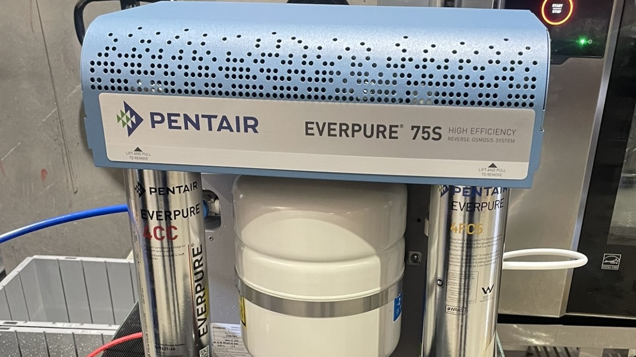
Everpure 75S RO system quick start guide
This is quick start guide for the Everpure 75S RO system. Please follow the Installation and operation instructions supplied with this unit for further technical support.
1
Step 1 of 17
<p>Installation process for 75S RO</p>

Installation process for 75S RO

2
Step 2 of 17
<p>Additional tools required to install and service this system.</p><ol><li>TDS Meter</li><li>Tyre Pressure gauge</li><li>Bike pump</li><li>Measuring jug ( Minimum size 500 ml)</li></ol>

Additional tools required to install and service this system.

  1. TDS Meter
  2. Tyre Pressure gauge
  3. Bike pump
  4. Measuring jug ( Minimum size 500 ml)
3
Step 3 of 17
<ol><li>Carefully lie the unit down on its back panel to allow access to the bottom of the white storage tank.</li><li>Remove blue dust cover to give access to the schrader valve</li><li>Adjust tank pressure to 24 PSI using pressure gauge and bike pump</li></ol>
  1. Carefully lie the unit down on its back panel to allow access to the bottom of the white storage tank.
  2. Remove blue dust cover to give access to the schrader valve
  3. Adjust tank pressure to 24 PSI using pressure gauge and bike pump
4
Step 4 of 17
<ol><li>Place unit on work bench and remove top blue cover.&nbsp; There are two screws either side of the blue cover.&nbsp;</li><li>Connect white water inlet tube into the right hand side JG 3/8 shut off valve ( A).&nbsp; With valve in the off position turn on water.</li><li>Remove 3/8" white JG plug from Tee piece on the top right hand side of unit (B).</li><li>Ensure tank is turned off using the the JG tank valve (C)</li><li>Connect blue tube into the Tee piece and place into suitable container for flushing.</li><li>Install the 4FC5-S cartridge into the first head assembly on right hand side.</li><li>Do not connect to power at this stage.</li></ol>
  1. Place unit on work bench and remove top blue cover.  There are two screws either side of the blue cover. 
  2. Connect white water inlet tube into the right hand side JG 3/8 shut off valve ( A).  With valve in the off position turn on water.
  3. Remove 3/8" white JG plug from Tee piece on the top right hand side of unit (B).
  4. Ensure tank is turned off using the the JG tank valve (C)
  5. Connect blue tube into the Tee piece and place into suitable container for flushing.
  6. Install the 4FC5-S cartridge into the first head assembly on right hand side.
  7. Do not connect to power at this stage.
5
Step 5 of 17
  1. Turn on inlet water and flush 4FC5 cartridge for 3- 5 minutes until water runs clear.
  2. Repeat this step using the 4CC cartridge in the same position on the unit and flush again for 3-5 mins until water runs clear.
6
Step 6 of 17
<p>Connect all cartridges in the correct order in the system including membrane.</p><p>4FC5 right hand side&nbsp;</p><p>4CC left hand side</p><p>GRO 75 Membrane fits behind 4FC5</p><p><br></p><p><br></p>

Connect all cartridges in the correct order in the system including membrane.

4FC5 right hand side 

4CC left hand side

GRO 75 Membrane fits behind 4FC5


7
Step 7 of 17
<p>GRO Membrane connections are colour coded</p><ol><li>White - water inlet at the top of the unit</li><li>Blue - permeate or product water&nbsp;</li><li>Red - waster water</li></ol>

GRO Membrane connections are colour coded

  1. White - water inlet at the top of the unit
  2. Blue - permeate or product water 
  3. Red - waster water
8
Step 8 of 17
<p>Turn the bypass valve clockwise finger tight until it is totally closed off.</p>

Turn the bypass valve clockwise finger tight until it is totally closed off.

9
Step 9 of 17
<p>Connect a 1 - 2 meter length of blue tube to the outlet of the system.</p><p>Connect the red waste line and discharge into a suitable drain.</p><p>Plug in power lead an turn on power.</p>

Connect a 1 - 2 meter length of blue tube to the outlet of the system.

Connect the red waste line and discharge into a suitable drain.

Plug in power lead an turn on power.

10
Step 10 of 17
<p>Install bypass plug in place of 4CC cartridge.</p><p>Turn on water supply and run for 10 -15 mins until TDS falls to 90 - 95% of the inlet tap water.&nbsp;</p><p><br></p><p><br></p>

Install bypass plug in place of 4CC cartridge.

Turn on water supply and run for 10 -15 mins until TDS falls to 90 - 95% of the inlet tap water. 


11
Step 11 of 17
<p>Record both the TDS of tap water and pure RO water for later use.</p>

Record both the TDS of tap water and pure RO water for later use.

12
Step 12 of 17
  1. Turn off power and water and allow system to stop producing water.
  2. Replace bypass plug with 4CC cartridge
  3. Turn on power and water outlet valve and allow water to flow for 5 mins.

13
Step 13 of 17
<p>With water running slowly open up the blending valve 1/4 turn at a time to reach a TDS of 50-70 ppm</p><p><br></p>

With water running slowly open up the blending valve 1/4 turn at a time to reach a TDS of 50-70 ppm


14
Step 14 of 17
<p>Blend the outlet water until we get a stable reading of TDS between 50-70 ppm.</p><p>Once the correct TDS is reached measure and record flow rate in mL/min&nbsp;<br></p>

Blend the outlet water until we get a stable reading of TDS between 50-70 ppm.

Once the correct TDS is reached measure and record flow rate in mL/min 

15
Step 15 of 17
<ol><p><span>When we have a stable outlet TDS of between 50 - 70 ppm the unit is now ready to be connected to the oven.</span></p><li><div>Turn off power and water.</div><div>Turn on tank, this is the blue JG tank valve that is visible (A)</div></li><li><div>Re fit blue cover.</div></li></ol>

    When we have a stable outlet TDS of between 50 - 70 ppm the unit is now ready to be connected to the oven.

  1. Turn off power and water.
    Turn on tank, this is the blue JG tank valve that is visible (A)
  2. Re fit blue cover.
16
Step 16 of 17
<p>System is now ready to be connected to the oven.</p>

System is now ready to be connected to the oven.

17
Step 17 of 17
<p>Record all measurements</p><ul><li>Inlet water TDS</li><li>Pure RO TDS</li><li>Blend TDS</li><li>Outlet flow mL/min</li></ul>

Record all measurements

  • Inlet water TDS
  • Pure RO TDS
  • Blend TDS
  • Outlet flow mL/min