

Remove one POWER plug ( of 2 ) from the main loom and remove CAN2 plug from the fly lead pictured.

Fit boot lace fitting to the POWER cable and CAN 2' fly lead as pictured.

Cable tie the other power lead back on the loom as pictured.

Start at the hose holder on the drawbar and run the ISOBUS (black & white) loom down to the front chassis cross member.

Feed the ISOBUS (black & white) loom under the chassis cross member then over the chassis rail out to the electronic enclosure on the right hand side as pictured.

Run the ISOBUS loom up to the top gland on the electronic enclosure as pictured.

Feed the (Power Cable) and (CANBUS IN Cable) into the top gland as pictured. the CANBUS plug will be a tight fit but will go through the gland.

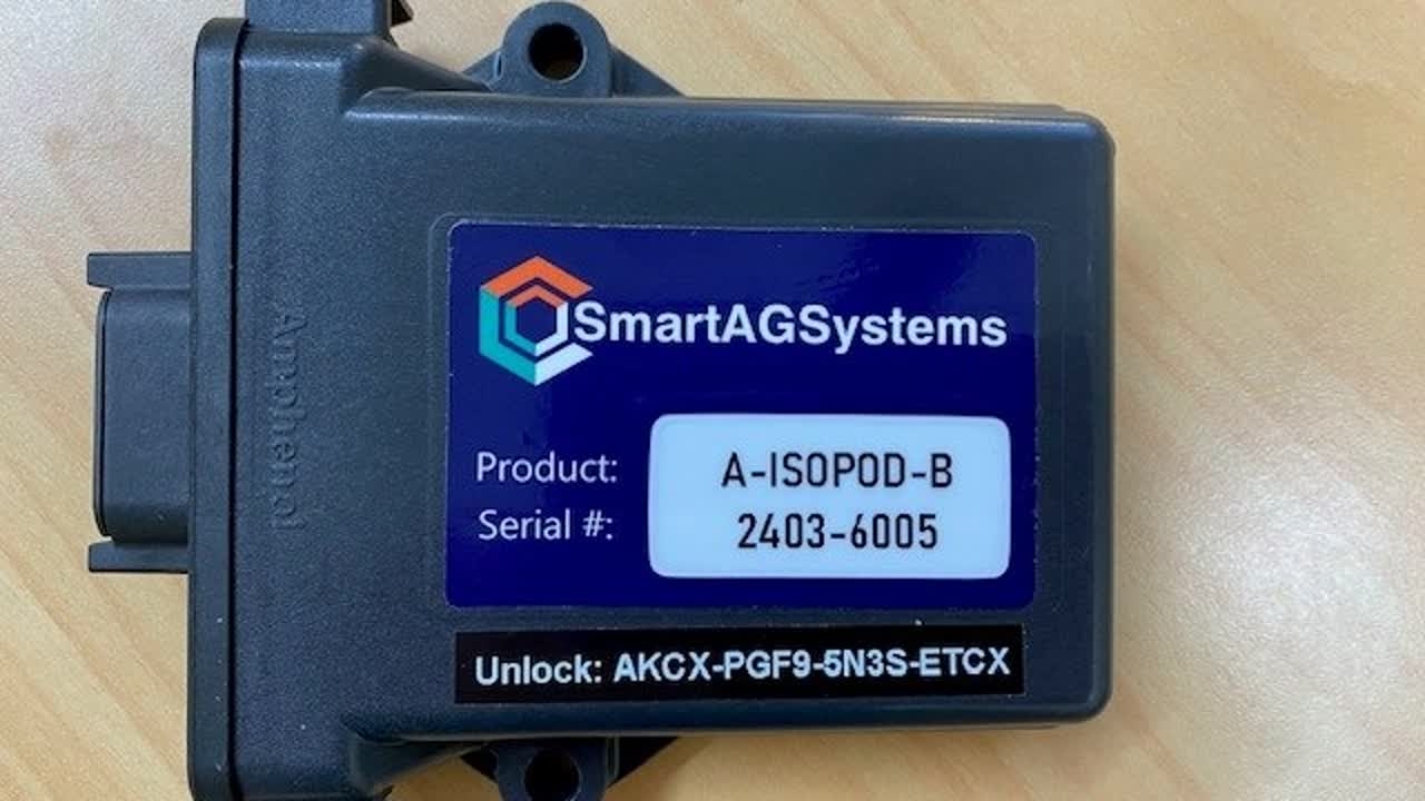
Add the new ISOPOD-B unit on top of the main Unipod as pictured.

Plug the fly lead loom into the ISOPOD-B and plug together CAN1 with CANBUS-IN as pictured.

Connect CAN2 wires in this postion and POWER wires in this postion on the main circuit board. Do not over tighten the clamps.

Fit new enclosure cover in place and secure the new loom in position as pictured.

Female ISOBUS plug from the spreader hose holder to the tractor.

Male ISOBUS plug on the back of the tractor.

Plug together as pictured

First tractor monitor screen.

Second tractor monitor screen.

Third tractor monitor screen.