
Certain files have been made available as standard documents shared across the team. This list can be grown. be aware that changing these files may affect other users.
Files stored in:
\Box\Operations\Product Design\Document Templates\Template Changover Files
MINIMUM: Update file path for
Sheet Metal Bend Line Note File
Sheet Metal Gauge Table
Alteratively, update all file paths that look like:
C:\Program Files\SOLIDWORKS Corp\SOLIDWORKS\lang\english
To:
\Box\Operations\Product Design\Document Templates\Template Changover Files\english
Note, a document template is different to a sheet format.
Drafting Standards:
\Box\Operations\Product Design\Sheet Formats\DDM
Document templates:
\Box\Operations\Product Design\Document Templates
With a file open, click customize and select the macros from the shown text file. Assign an appropriate key to use these. These will be used throughout this knowby.
Text file:
(C:\Users\MacHildebrandUtemast\Box\Operations\Product Design\Document Templates\Template Changover Files)
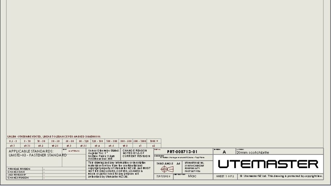
From an existing A4 drawing, apply macro: APPLY A3 TEMPLATE.swp and then APPLY A4 TEMPLATE.swp to use the new template. Only applying the A4 template seems to run into issues.
Note the material and thickness have not been transferred.
If the colour of your templates is strange, check the layers options and colours. These can remain with the user or previous document so worth changing to what you want them to be (black for all, grey for borders, white to standards)
This shows how to see the formula each field runs on. if you wish to change a field, type a $ in the field. Most of these fields pull from the document using $PRP:"___" or $PRPSHEET:"___". More of these field codes are available online.
To apply material to the drawing, select a material to apply to the part. This can be any material.
Only gauge tables pull material thickness data through to the drawing. the material thickness must be set using a gauge table. Use All k0.4 to have all settings available. This file is best directed to in a standalone folder to show only 1 option unless you need more precision.
e.g. C:\Program Files\SOLIDWORKS Corp\SOLIDWORKS (2)\lang\english\Sheet Metal Gauge Tables\Mac
Finally, run macro Custom Summary Info.swp to link the properties from the part file to the drawing.
When creating a new part using the new Document template - Custom Summary Linked, this will already be done.
If you do not want to link the properties from the part file or want to add custom fields, use the macro Mat spec.swp.
This shows how it adds text in the correct locations. Click A3 if you are working on an A3 drawing.
Please note this deletes the text link between the part and the drawing.
If your formatting for the drawing is not all the same, use 2.5mm text all.swp to make all the text 2.5mm tall and ISO-modified.
The macros which apply these templates will need to be modified if you are wanting to use the drafting standard ISO-Modified which changes all text to black and 2.5mm tall.
The file path needs to be changed to C:\Users\_NAME_\Box\Operations\Product Design\Document Templates\Template Changover Files\ISO-MODIFIED.sldstd
Copy the macro for A4 and ISO-Modified and save adding your name with the updated directory.