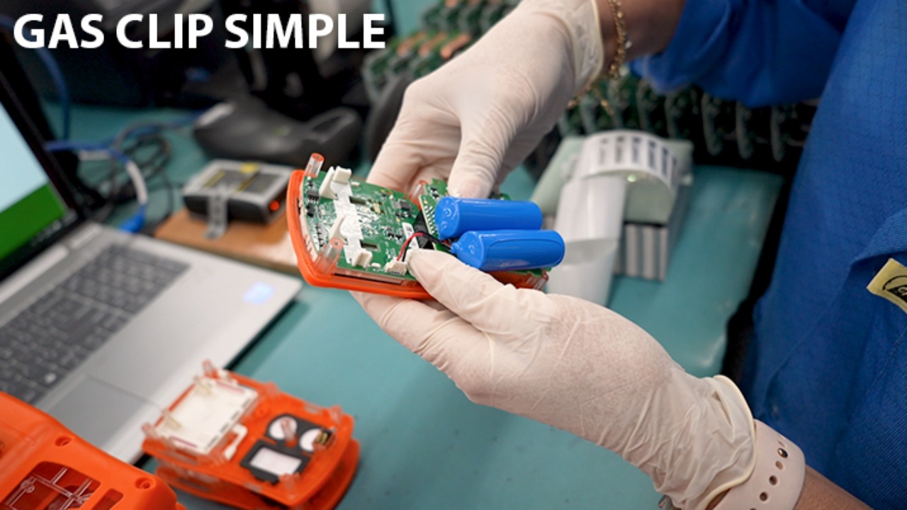
Station 1: Programming
Brush off connector points on the boards
Snap the frame off
Connect the board halves
Trim board tips
Separate the boards
Station 1: Programming
Place the board in reader
Press the Up Arrow then Enter to start the program
Wait for programming to complete
Press power button for light confirming programming is complete
Apply S/N label to finishing
*make sure you have the correct labels for the current model. They all look the same
Station 2: Front Assembly
Peel screen film off. Examine case for any defects/blemishes
Blow off any dust with the air the compressor
Place the gasket in the screen cavity
Take film off LCD front and insert into case front
Station 2: Front Assembly
Insert Both Zebra Strips
*Do not touch center layer with hands, oil will damage it
Apply filters (2 round, 1 rectangle)
Insert vibrator
Station 2: Front Assembly
Insert foam gaskets
Pass to next station
Station 3: Configuration
Take a board. Apply a spacer and sensors.
*be sure to remove the wire spring on the four-pronged sensor if present
Scan the four different QR codes (sensors and board)
Station 3: Configuration
Connect battery then press front button to confirm power
Snap in board to case front then press screen in to verify LCD and zebra strips function
Place in front of IR scanner
Station 3: Configuration
Apply sticker to the case back and scan into computer. Confirm green "success" message in software
Combine back and front. Then pass on to next station
Station 4: Closing
Inspect case back and buff out any blemishes.
Screw down metal clip
Station 4: Closing
Insert the 3 screws (009-0420) and then screw down board into case front
Place battery spacer and add battery
Tuck in wires
Station 4: Closing
Snap on case back and insert the 6 screws. Screw down all but one screw
*hold drill straight. Drill will stop on it's own
Station 4: Closing
Verify seam has proper seal and adjust if needed. Screw in final screw and check seam again
Pass to final station
Station 5: Calibration
Place unit in front of IR scanner and power down using the software.
Then hold power button to turn back on. Confirm vibrator and backlights work.
Inspect unit for any defects
Station 5: Calibration
Apply back sticker
Remove excess rubber if necessary then apply front bubble sticker
Station 5: Calibration
Place units in calibrator. Press the red "Bump Test" button and wait a couple minutes until lights turn green.
Then press the green "Calibration" button and wait a few minutes until lights turn green
Station 5: Calibration
Combine the manual with the calibration certificate.
Apply sticker label to the side of the box
*Always make sure the unit, box label and certificate all have matching serial numbers
Station 5: Calibration
Place unit, papers, and attachment in the box
Double check all three serial numbers match. And then pass on to QC