
Knowby
TC - SBD Centre Drawer Retro Fit
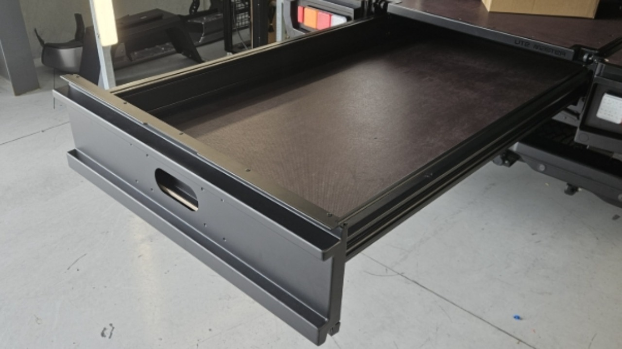
How to retro fit a centre drawer to a Trailcore service body.
1
Step 1 of 41
<p>Slide 1 bearing thread plate down the centre extrusion from the front of the service body.</p><blockquote><p><strong>CQC: </strong>Ensure the 2 hexagon cut-outs are positioned at the bottom rear.</p></blockquote><p></p>

Slide 1 bearing thread plate down the centre extrusion from the front of the service body.

CQC: Ensure the 2 hexagon cut-outs are positioned at the bottom rear.

2
Step 2 of 41
<p>Slide 2 catch thread plates down the centre extrusion, behind the oblong pilot cut-outs.</p>

Slide 2 catch thread plates down the centre extrusion, behind the oblong pilot cut-outs.

3
Step 3 of 41
<p>Preassemble 2 catches using the parts shown.</p>

Preassemble 2 catches using the parts shown.

4
Step 4 of 41
<p>Install the catches to the service body.</p><blockquote><p><strong>CQC: </strong>Ensure the catches are installed to the pilot cut-out, and the catch sits pressed up against the body extrusion.</p></blockquote><p></p>

Install the catches to the service body.

CQC: Ensure the catches are installed to the pilot cut-out, and the catch sits pressed up against the body extrusion.

5
Step 5 of 41
<p>Repeat for the other side.</p>

Repeat for the other side.

6
Step 6 of 41
<p>Run foam tape along the bracing in the positions shown.</p>

Run foam tape along the bracing in the positions shown.

7
Step 7 of 41
<p><span style="font-size: 22px; line-height: 1.4;">Install the drawer bearing between the two bearing brackets in the following order:<br>M10 BTN bolt → Bracket → M10 flat washer → Bearing → M10 flat washer → Bracket → M10 nyloc nut.<br>Tighten using a 6 mm hex bit and a 17 mm spanner.</span></p><blockquote style="background-color: rgb(223, 231, 248);"><p><strong>CQC: </strong>Ensure M10 flat washers are used either side of the bearing to allow it to move freely.</p></blockquote><p></p>

Install the drawer bearing between the two bearing brackets in the following order:
M10 BTN bolt → Bracket → M10 flat washer → Bearing → M10 flat washer → Bracket → M10 nyloc nut.
Tighten using a 6 mm hex bit and a 17 mm spanner.

CQC: Ensure M10 flat washers are used either side of the bearing to allow it to move freely.

8
Step 8 of 41
<p>Install the bearing brackets to the rear centre cross member using 4x M8x50mm button head bolt and M8 nyloc nuts.</p><p>Tighten all bolts.</p>

Install the bearing brackets to the rear centre cross member using 4x M8x50mm button head bolt and M8 nyloc nuts.

Tighten all bolts.

9
Step 9 of 41
<p>Rivet the 2 cover plates to the rear of the body.</p>

Rivet the 2 cover plates to the rear of the body.

10
Step 10 of 41
11
Step 11 of 41
<p>Rivet the dust covers to the cross members.</p><p><em>Note: If the front rivets are too hard to access from underneath the body, run a bead of SMP60 silicone across the top of the front cross member to keep the front of the dust cover fixed in place.</em></p>

Rivet the dust covers to the cross members.

Note: If the front rivets are too hard to access from underneath the body, run a bead of SMP60 silicone across the top of the front cross member to keep the front of the dust cover fixed in place.

12
Step 12 of 41
<p>Rivet the number plate light contact plunger to the body.</p><blockquote><p><strong>CQC: </strong>Ensure the rubber shroud is riveted behind the plate.</p></blockquote><p></p>

Rivet the number plate light contact plunger to the body.

CQC: Ensure the rubber shroud is riveted behind the plate.

13
Step 13 of 41
<p>Slide the drawer into the body.</p><p><em>Note: Manually unlatch to slide the drawer past the first set of catches.</em></p>

Slide the drawer into the body.

Note: Manually unlatch to slide the drawer past the first set of catches.

14
Step 14 of 41
<p>Preassemble 3 bearing stacks in this order: Bearing shaft<span style="font-size: 22px; line-height: 1.4;"> → rubber o-ring → Bearing → rubber o-ring → M10 spacer.</span></p><blockquote style="background-color: rgb(223, 231, 248);"><p><strong>CQC: </strong>Ensure Loctite thread locker is applied to the thread of each bearing shaft.</p></blockquote><p></p>

Preassemble 3 bearing stacks in this order: Bearing shaft → rubber o-ring → Bearing → rubber o-ring → M10 spacer.

CQC: Ensure Loctite thread locker is applied to the thread of each bearing shaft.

15
Step 15 of 41
<p>Pre assemble the LH bearing plate with the bearing plate washer behind the bearing plate.</p>

Pre assemble the LH bearing plate with the bearing plate washer behind the bearing plate.

16
Step 16 of 41
<p>Wind each bearing shaft into the bearing thread plate, then tighten all 3 bearing shafts.</p>

Wind each bearing shaft into the bearing thread plate, then tighten all 3 bearing shafts.

17
Step 17 of 41
<p>Preassemble the RH bearing shafts: Bearing shaft<span style="font-size: 22px; line-height: 1.4;"> → bearing. </span></p><blockquote style="background-color: rgb(223, 231, 248);"><p><strong>CQC: </strong>Ensure Loctite thread locker is applied to the thread of each bearing shaft thread.</p></blockquote><p></p>

Preassemble the RH bearing shafts: Bearing shaft → bearing.

CQC: Ensure Loctite thread locker is applied to the thread of each bearing shaft thread.

18
Step 18 of 41

Repeat step 15 on the RH side bearings.

19
Step 19 of 41
<p>Slide the LH runner extrusion onto the drawer side cap.</p>

Slide the LH runner extrusion onto the drawer side cap.

20
Step 20 of 41
<p>LH extrusion.</p>

LH extrusion.

21
Step 21 of 41
22
Step 22 of 41
<p>LH extrusion - t-track slot at the rear.</p>

LH extrusion - t-track slot at the rear.

23
Step 23 of 41
<p>Slide the LH extrusion runner to meet the drawer carriage.</p>

Slide the LH extrusion runner to meet the drawer carriage.

24
Step 24 of 41
<p>Repeat for the RHS extrusion runner.</p>

Repeat for the RHS extrusion runner.

25
Step 25 of 41
<p>Fix the LH extrusion runner to the drawer carriage using 2 M8x50mm bolts, with a spring and flat washer as shown.</p><blockquote><p><strong>CQC:</strong> Ensure loctite thread locker is applied to the thread of each bolt.</p></blockquote><p></p>

Fix the LH extrusion runner to the drawer carriage using 2 M8x50mm bolts, with a spring and flat washer as shown.

CQC: Ensure loctite thread locker is applied to the thread of each bolt.

26
Step 26 of 41
<p>Repeat for the RH extrusion runner.</p>

Repeat for the RH extrusion runner.

27
Step 27 of 41
<p>Sit the backing plate over the front of the plywood.</p>

Sit the backing plate over the front of the plywood.

28
Step 28 of 41
<p>Fix the backing plate to the drawer extrusion runners using 4 M8x50mm bolts, with a spring and flat washer as shown.</p><blockquote><p><strong>CQC:</strong> Ensure loctite thread locker is applied to the thread of each bolt.</p></blockquote><p></p>

Fix the backing plate to the drawer extrusion runners using 4 M8x50mm bolts, with a spring and flat washer as shown.

CQC: Ensure loctite thread locker is applied to the thread of each bolt.

29
Step 29 of 41
30
Step 30 of 41
<p>Clamp the backing plate to the plywood using 4x M6x25mm hex bolts and nyloc flange nuts.</p>

Clamp the backing plate to the plywood using 4x M6x25mm hex bolts and nyloc flange nuts.

31
Step 31 of 41
<p>Slide the LH rod through the LH runner extrusion.</p>

Slide the LH rod through the LH runner extrusion.

32
Step 32 of 41
<p>Hook the rod into the catch.</p>

Hook the rod into the catch.

33
Step 33 of 41
<p>Rotate the rod into the drawer handle.</p>

Rotate the rod into the drawer handle.

34
Step 34 of 41
<p>Repeat for the RHS.</p>

Repeat for the RHS.

35
Step 35 of 41
<p>Check drawer functionality.</p>

Check drawer functionality.

36
Step 36 of 41
<p>Plug the female blade terminals of the number plate lights on the faceplate into male terminals on the backing plate.</p>

Plug the female blade terminals of the number plate lights on the faceplate into male terminals on the backing plate.

37
Step 37 of 41
<p>Sit the faceplate over the backing plate, then rivet into position.</p>

Sit the faceplate over the backing plate, then rivet into position.

38
Step 38 of 41
39
Step 39 of 41
<p>Slide 3 t-track thread plates into the drawer extrusion, then fix the latch cover to the drawer carriage using 8 M8x12mm flange bolts.</p>

Slide 3 t-track thread plates into the drawer extrusion, then fix the latch cover to the drawer carriage using 8 M8x12mm flange bolts.

40
Step 40 of 41
<p>Repeat for the other side.</p>

Repeat for the other side.

41
Step 41 of 41

Terminate existing number plate light vehicle loom with 2 female blade terminals (provided) and plug into the rear of the plunger.