
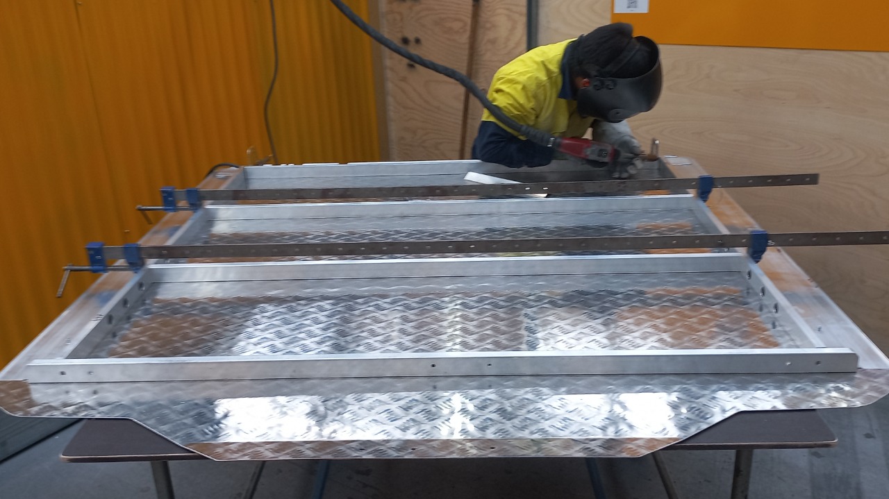

Match job card to lid shell model
Wire brush any swarf/burrs from the "weld groove"

Take lid shell from trolley & place it tread side down on table.
Ensure both sides of lid shell overhang the table enough to fit extrusion. Make sure you are working on a clean table to avoid scratches

Get extrusion from trolley and set out on lid shell

Check for defects, clean any cutting fluid residue with wax & grease remover
Fit m6 studs to both side rails. Use an m6 flange nut and m6 washer to seat the stud. Stud locations vary between models
Clip side rails onto lid, Use rubber mullet to fully seat side rail extrusion to the lid shell
The "logo cut out" should be at the front of the lid shell
Sit front hinge extrusion and rhs into place
Take note of how the rear rhs is fitted the square cutouts need to be facing towards the front of the lid
Use big clamps to clamp the center rhs with tops flush.
NOTE:
Do not over tighten clamps it will cause the rhs to bow in the middle

Clamp front extrusion into place ensure it's centered between the side rail extrusion

Set welder to job #3 thickness 3.6 Tack all RHS as shown. The circled areas weld both sides of RHS, The arrows indicate only weld this side
QCQ: There should be no gap between the RHS & lid shell
Make sure rear rhs is straight and weld the middle 25mm long
Weld all corners as shown. Repeat for the opposite side of the lid (left or right depending what side you started on)
Use welding jig for weld size and spacing. weld three welds from each side of the lid then one weld in center of each RHS
Weld corners of siderail extrusion as shown, ensure weld does not stick up too much above extrusion.
Starting from one side, use 2 locking clamps and clamp 2-3 holes apart.
Use welder on job #4 (thickness should be preset at 5.2)
Once you have completed those holes, move clamps and repeat.

Completed underside welding
NOTE: The hinge extrusion welds and corner welds should be the only welds visible from the rear

All welds complete
Front of RHS welded. All corners welded. Hinge extrusion welded and spot welds complete
![<p>Sand any defects from underside of lid using P60 sandpaper. [Scratches, weld splatter]</p>](https://knowby.show/media/5f9f8fee-b577-42c1-9b91-0984bbc59290/knowbys/3482335e-4557-41bc-98f6-fe26baf5bbbd/steps/83d68094-4c37-4f65-8b08-8038bb696f89/448141b5-6c02-4937-aba4-3c1d0192d343-web.jpg)
Sand any defects from underside of lid using P60 sandpaper. [Scratches, weld splatter]

Flip lid so tread is side up
All MIG WELDING HELMETS MUST BE REMOVED FROM THE LASER BAY BEFORE LASER WELDING STARTS
Laser weld all the joins on the top side as shown. Set welder to custom job #1 check settings match these
Laser welder settings:
80% power
55 hz
4.2 wobble
135 wire feed
welding wire: Grade 5356,
1.6mm diameter
Laser settings may need to be adjusted slightly
Never use laser welder unless trained and competent. See your team leader if untrained
SLR5000 Laser Welder Safety
SLR5000 Laser Welder Operation
QC welds and ensure that there is no holes or missed spots. If there is something missed do another pass with the laser welder over that spot.
CQC: Any pinhole or incomplete weld on the top side will cause a water leak. Take the time to inspect your welds properly

The weld on the end of extrusion at both ends needs to be as small as possible to ensure the end cap will fit in final assembly
Give side rails a quick "10 second" sand per side. Deeper scratches may require a little extra
Sand any sharp edges from handle end of lid

Edges should be like this when done. No sharp edges
NOTE: This edge is left exposed after assembly i.e. no wind lace on this edge.
Check topside of spot welds for over penetration carefully grind or sand if any have penetrated out the topside of the lid
Hang lid with side rails vertical and handle end at the bottom, blow down for PC.
FINAL QC LID
Check all threads
Branding plate holes
Hinge holes have been plugged with silicone plugs.
Blow down all surfaces ready for pc