
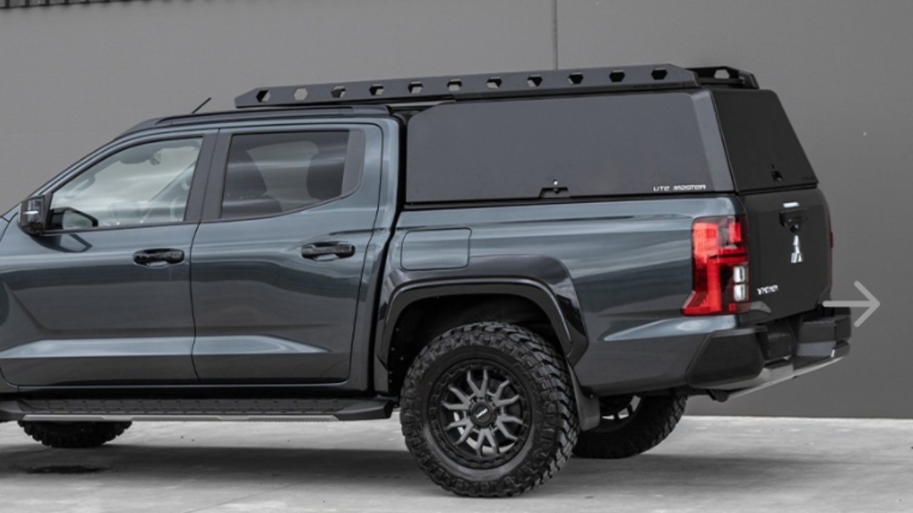
This guide is detailed for MK3 and MK4 canopies with factory supplied CLK installed.
Canopy Central locking should follow the lock and unlock of the vehicle:
Vehicle Lock = Canopy Lock
Vehicle Unlock = Canopy Unlock
Any door open = Power to lighting
All Doors closed = No power to lights
Verify power feed to canopy by turning on rear door interior LED.
Lighting fault - remove the lock cover to verify spade termination onto switch assembly and power feed to light is connected and insulated. Confirm there are no exposed wires or short circuits.
If Central Locking and internal lights won't turn on, check the fuse hasn't blown.
This is located in the engine bay a short distance from the positive battery terminal.
Replace fuse if blown, re-test the lighting and central locking.

If one LED light won't power on, however all other functions operate correctly, remove the lock cover, and bench test the light using a 12v battery to confirm if this is faulty.
Emergency latch should operate smoothly on all doors. Pulling up vertically on lever will allow the door to open.
Any binding or stuck in position - remove the lock cover and inspect.
Door switches control isolation of Lock & Unlock relays & internal lighting power feed
One door open, (or a switch not fully engaged when the door is closed), power will be provided to the LED light circuit and power cut to the central locking circuit.
All doors closed will provide power to the central locking circuit and cut power to the LED light circuit.
When pressing the door switch with one door open, an Audible switching of relays should be heard alongside light power switching.

Shall any door not have any CLK and power, and other doors switch the relays - inspect door sub-loom connections located above each door for complete connection
Notes:
No connection, or a broken connection will act like a closed door
Visually inspect pin-out for any damage
If LED is operational, inspect the door switch connection (spade terminal + ring terminal)
Check for any wear, pinching or cut on wires near switch assembly

Verify vehicle to canopy connection at loom interface located at front left of tub/wellside - ensure solid connection.
Ensure the wiring is free from any wear or chafing.
This is the position to remove connector shall further diagnostic be required
Check latch to switch plunger alignment - Ensure plunger is fully engaging with latch
Inspect by holding the emergency latch on the door cover and closing the door.
The door switch should activate after approx. 3mm of compression. (you should hear the relays clicking as this engages)
If this is misaligning, click here:
How to fix canopy door switch misalignment.
NOTE: If the switch is too long, this can over-stress the switch causing this to break. These can be trimmed using wire cutters.
Specifically check the rear door latch alignment - if the lock strike is loose, this will cause the switch to rotate the lock strike instead of engaging the switch.
Tighten M10 fastener as required.

Inspecting the wiring beneath the canopy door covers, as this area is particularly susceptible to damage or pinching.
Verify no shorts between any latch components
Image shows door cover/switch bracket assembly
Using the vehicle model specific central locking install instructions, check the vehicle battery positive, and earthing connection points.
Check any central lock connection points.
(Either plug and play, or crimp connections)
Verify no damage to loom between canopy and vehicle connection points

Relay location is passenger side inside front pillar - either behind the relay cover or electrical panel
Undone by removing the 3 x M6 fasteners, IF a front wall Muletek panel is fitted, remove fasteners from both sides

End Connector Pin-Out
RED - Power
BLACK - Ground
BLUE - Unlock
GREEN - Lock
BLANK
BLANK
To verify canopy loom is defective (removing vehicle potential) - power Pin 1, ground Pin 2 (this will power lighting circuit when doors open)
pulse Pin 3 or 4 to cycle Unlock/Lock cycles (all doors need to be closed to energize CLK relays)

Front Wall Relay Call out
Unlock
Lock
Power (CLK relay feed + Light)

Door Loom
Green
Purple
Black