Knowby Heg Automotive Pty Ltd
Knowby
OTA Switch Installation & Wiring Instructions
1
Step 1 of 3
<h1>Before You Start</h1><p></p><p>•&nbsp;&nbsp;&nbsp;&nbsp; <strong>Disconnect the battery negative terminal</strong> before doing any wiring.</p><p>•&nbsp;&nbsp;&nbsp;&nbsp; Check behind the panel before drilling or cutting. Avoid airbag wiring and existing looms.</p><p>•&nbsp;&nbsp;&nbsp;&nbsp; <strong>Always wire the switch through a fused relay.</strong> The switch only triggers the relay. Never run LED lights, compressors or other accessories directly through the switch.</p><p>•&nbsp;&nbsp;&nbsp;&nbsp; Fuse the switch supply close to the battery.</p><p>•&nbsp;&nbsp;&nbsp;&nbsp; If unsure, have the job done by a qualified auto electrician.</p><p></p><h1>Tools Required</h1><p></p><p>Multi meter, wire strippers, crimp tool, drill (if cutting a new switch hole), heat-shrink, cable ties, inline fuse holder, ring terminal for earth.</p><h1></h1><p></p><p></p><p></p>

Before You Start

•     Disconnect the battery negative terminal before doing any wiring.

•     Check behind the panel before drilling or cutting. Avoid airbag wiring and existing looms.

•     Always wire the switch through a fused relay. The switch only triggers the relay. Never run LED lights, compressors or other accessories directly through the switch.

•     Fuse the switch supply close to the battery.

•     If unsure, have the job done by a qualified auto electrician.

Tools Required

Multi meter, wire strippers, crimp tool, drill (if cutting a new switch hole), heat-shrink, cable ties, inline fuse holder, ring terminal for earth.

2
Step 2 of 3
3
Step 3 of 3
<h1>Installation</h1><p></p><p>1.<span>&nbsp;&nbsp;&nbsp;&nbsp;&nbsp; </span>Disconnect the battery negative terminal.</p><p>2.<span>&nbsp;&nbsp;&nbsp;&nbsp;&nbsp; </span>Choose a switch position within easy reach of the driver. Use a spare switch blank if one is available, or cut a hole to suit the switch.</p><p>3.<span>&nbsp;&nbsp;&nbsp;&nbsp;&nbsp; </span>Plug the wiring harness into the back of the switch until it clicks.</p><p>4.<span>&nbsp;&nbsp;&nbsp;&nbsp;&nbsp; </span>Run the harness to the battery, earth points, relay and dash light circuit. Use existing grommets through the firewall and keep wiring away from heat and moving parts.</p><p>5.<span>&nbsp;&nbsp;&nbsp;&nbsp;&nbsp; </span><strong>Pin 1 Black and Pin 4 White: </strong>fit ring terminals and connect both to a clean, bare-metal chassis earth or battery negative.</p><p>6.<span>&nbsp;&nbsp;&nbsp;&nbsp;&nbsp; </span><strong>Pin 2 Green: </strong>connect to the relay trigger terminal.</p><p>7.<span>&nbsp;&nbsp;&nbsp;&nbsp;&nbsp; </span><strong>Pin 5 Red: </strong>connect to +12 V through the inline fuse. Leave the fuse out for now.</p><p>8.<span>&nbsp;&nbsp;&nbsp;&nbsp;&nbsp; </span><strong>Pin 6 Yellow: </strong>connect to the dash light circuit.</p><p>9.<span>&nbsp;&nbsp;&nbsp;&nbsp;&nbsp; </span>Crimp and heat-shrink all joins. Secure the harness with cable ties.</p><p>10.<span>&nbsp;&nbsp; </span>Fit the fuse and reconnect the battery.</p><p>11.<span>&nbsp;&nbsp; </span>Test the switch (below), then push it firmly into the panel.</p><p></p><h1>Testing</h1><p></p><p>1.<span>&nbsp;&nbsp;&nbsp;&nbsp;&nbsp; </span>Turn the dash lights on. The switch backlight should come on.</p><p>2.<span>&nbsp;&nbsp;&nbsp;&nbsp;&nbsp; </span>Press the switch. The accessory should turn on.</p><p>3.<span>&nbsp;&nbsp;&nbsp;&nbsp;&nbsp; </span>Press again. The accessory should turn off.</p><p></p><p>If nothing works, check the fuse and the earth connection first. If the switch lights up but the accessory does not turn on, check the green wire (pin 2) and the relay.</p>

Installation

1.      Disconnect the battery negative terminal.

2.      Choose a switch position within easy reach of the driver. Use a spare switch blank if one is available, or cut a hole to suit the switch.

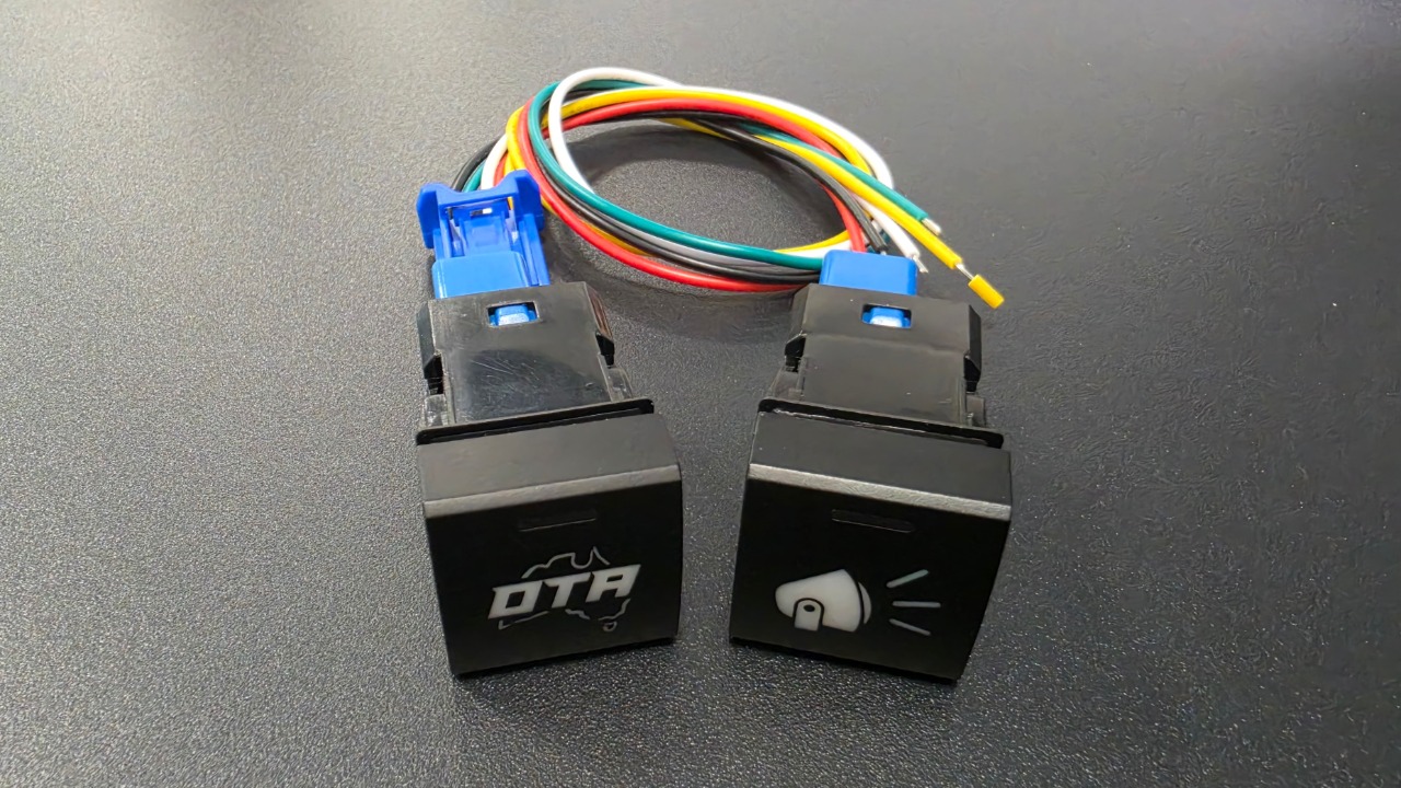
3.      Plug the wiring harness into the back of the switch until it clicks.

4.      Run the harness to the battery, earth points, relay and dash light circuit. Use existing grommets through the firewall and keep wiring away from heat and moving parts.

5.      Pin 1 Black and Pin 4 White: fit ring terminals and connect both to a clean, bare-metal chassis earth or battery negative.

6.      Pin 2 Green: connect to the relay trigger terminal.

7.      Pin 5 Red: connect to +12 V through the inline fuse. Leave the fuse out for now.

8.      Pin 6 Yellow: connect to the dash light circuit.

9.      Crimp and heat-shrink all joins. Secure the harness with cable ties.

10.   Fit the fuse and reconnect the battery.

11.   Test the switch (below), then push it firmly into the panel.

Testing

1.      Turn the dash lights on. The switch backlight should come on.

2.      Press the switch. The accessory should turn on.

3.      Press again. The accessory should turn off.

If nothing works, check the fuse and the earth connection first. If the switch lights up but the accessory does not turn on, check the green wire (pin 2) and the relay.