

Table of Contents
Planter Safety
BOSS Bridge Frame
Road/In-Field Travel
Hooking Up
Setting Frame Operating Height
Folding Procedure
Outer Wing Wheel Lockout
Important Bolts to Check
Maintenance
Grease Points
Further Assistance
Planter Safety
Read and understand the operators manual before using this equipment.
Ensure safety stands are in place before working under machine.
Ensure the tractor is shut down and the key removed before working on machine.
Be aware of pinch points on the row units and planter frame.
Ensure the machine is securely chocked when unhooking to prevent the machine from rolling.
Do not disconnect hydraulic breakaway couplings while the hydraulic system is under pressure.
Inspect for hydraulic leaks and replace hoses if required. Do not inspect for oil leaks with bare hands as small invisible high pressure oil leaks can penetrate the skin and require treatment.
Pressurised hydraulic oil can harm or kill.
Never ride on machine when operating.
Do not let children climb or play on machine.
Ensure safety pins are in place when the machine is in the folded position.
Ensure the tractor is ballast correctly for linkage machines.
Be aware of overhead powerlines when transporting a folded machine.
Width and height restrictions may apply when travelling on public roads, consult your local transport regulator for specific requirements in your area.
Max travelling speed is 20km/h.
Ensure tyres are inflated to the correct pressure as recommended.
Inspect the machine regularly for loose bolts, damaged or worn components and replace as required.
Inspect and keep wheel studs tight.
Do not stand between the tractor and implement while coupling the machine up.
Ensure all safety signs are in place and replace if damaged.
Ensure all safety guards are in place.
No persons within 50 metres when the machine is operating.

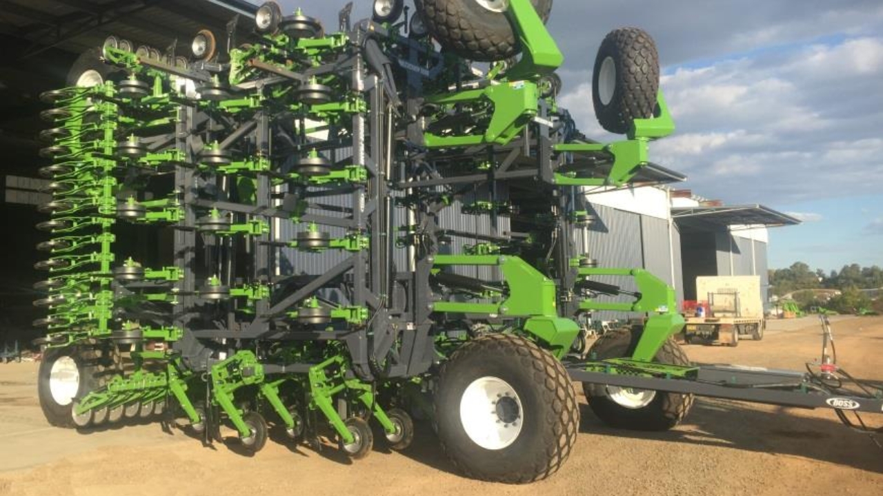
BOSS Bridge Frame Overview
Road & Field Travel
BOSS planters are designed primarily for in field operation, this means tyre selection and position is for optimum in field use. Continuous high speed road travel is not recommended as this is not the machines primary design function.
We understand road travel may be required from time to time and as such certain steps/guidelines need to be considered for personal and public safety and to avoid tyre damage.
Always use an agricultural tractor large enough and with sufficient braking capacity to stop the combined unit quickly and safely.
Make sure tyre pressures are correct as per operators manual or inflation stickers located on the rim.
Ensure all wheel nuts are present and tight as per operators manual or wheel nut torque stickers located on the rim.
Make sure connection pin and hitch components are in good order with no possibility of the machine coming unhooked.
Travel Speed should not exceed 20km per hour.
Know the machines limitations when negotiating changes in road conditions. Reduce speed over uneven or rough terrain and be aware of hazards such as bridges, trees, fences, power lines and other road users.
Machines are often oversize and as such follow local laws regarding excess dimension transport requirements.
Exercise caution when transporting BOSS Planters on public roads in poor visibility or when road conditions are wet as stopping capability may be reduced.
Be aware of overhead powerlines at all times.
Do not allow anyone to ride on the machine at any time.
High road temperatures significantly reduce tyre carrying capacity, stop and check tyres regularly and allow to cool before continuing.
Ensure fold safety pins are in place and any components fitted to the machine cannot fall off during transport.
It is important to remember that BOSS Planters are NOT designed for frequent, high speed or long distance road transport and as such BOSS Agriculture does NOT recommend on road travel other than necessary, infrequent, short distance road travel at a reduced speed following above guidelines.

Hooking Up
Ensure no-one is at risk of being crushed or trapped before commencing to hook up the machine to the tractor, use the mechanical parking jack stand to set the drawbar pull to the correct height before reversing.
Connect all hydraulic lines making sure all hydraulic fittings are clean prior to connection. All hydraulic dump lines are required to be connected correctly to avoid damage to the machine, row units or air seeder. BOSS dump lines are generally labelled however ensure you have an understanding of the machines operation and connect hydraulic lines accordingly.
Connect electrical wiring harnesses (if applicable).
The main hitch pin should be the correct size for both the machine and the tractor (use as large a pin as possible) the pin should be undamaged and in good condition.
Once the tractor and machine are connected remove the parking jack and place in the storage position.

Setting Frame Operating Height
Frame operating height is set by adjusting the ram stops located on the in-frame centre section cylinders.
Using a ¾ spanner, loosen ram stops and adjust all 4 stops (2 on each cylinder) to achieve the required under-bar operating height. These stops MUST be adjusted EVENLY and a preferred method is to check with a ruler. If they are not adjusted evenly the cylinder rod can become fatigued and break off. Once all stops are evenly adjusted, tighten the locating bolts.
The correct operating height is determined by the row unit that is fitted to the frame; refer to the row unit operating manual for instruction on frame height.
Folding Procedures
Single Fold Machines
Double Fold Machines with Lockout

Folding Procedure - Single Fold Machines
WARNING:
Be aware of the height of the frame when working around power lines.
Ensure no-one is under the wing section at any time.
Folding Procedure - Single Fold Machines
Prior to folding your machine ensure the lift cylinders are phased correctly and the frame is level. To phase the cylinders fully raise the frame and hold levers on momentarily then lower slightly and repeat to allow the oil to fill lines and cylinders completely to ensure phasing poppets are correctly seated.
When folding the Bridge Frame a tractor must be hooked up to the machine and the terrain must be level and safe.
Ensure the area is clear of power lines, trees and people in the vicinity of the machine are far enough away to be safe.
Ensure fold safety pins are in the storage position so no damage can occur to fold cylinders when operating.
Before folding raise the machine so the row units are off the ground and ensure the row units do not drag across the ground as the wings are coming up. The wings should operate together, and both should come up evenly. If the wings are not coming up together do not continue to fold and contact a BOSS representative for further instruction.
Once the machine is fully folded, the safety fold pins should be placed in the transport position (located on inner wings only).
When unfolding the Bridge Frame, remove the safety fold pins and ensure the area is clear and safe. Once the machine has been unfolded continue to extend fold cylinders until they are all the way out (approx. halfway in the operating slot) this will allow the wing sections to float up or down and follow ground contours without damaging hydraulic cylinders.


Folding Procedure - Double Fold Machines with Lockout
WARNING:
Be aware of the height of the frame when working around power lines.
Ensure no-one is under the wing section at any time.
Folding Procedure - Double Fold Machines with Lockout
Warning: Large double fold machines should not have castor arms put under load when the machine is folded. Lower the frame stands so front castor wheels can be manually turned to the reversing position or forward position as required.
Prior to folding your machine ensure the lift cylinders are phased correctly and the frame is level. To phase the cylinders fully raise the frame and hold levers on momentarily then lower slightly and repeat to allow the oil to fill lines and cylinders completely to ensure phasing poppets are correctly seated.
When folding a Bridge Frame with a double lockout fold a tractor must be hooked up to the machine and the terrain must be level and safe. Ensure the area is clear of power lines, trees and people in the vicinity of the machine are far enough away to be safe.
Ensure fold safety pins are in the storage position so no damage can occur to fold cylinders when operating.
The double fold system on Bridge Frames operates through two separate hydraulic systems:
The inner wing fold
The outer lockout fold
Before folding raise the machine so the row units are off the ground and ensure the row units do not drag across the ground as the wings are coming up.
Folding machine: Activate the inner wing fold until the outer wing wheels are clear of the ground, once the wing wheels are off the ground activate the outer lockout fold until the outer wing is completely folded, you can now fully fold the inner wing.
Once the machine is fully folded the safety fold pins should be placed in the transport position (located on inner wings only).

STEP 1: Bridge Frame Folding Procedure
Ensure row units are off the ground before attempting to fold.

STEP 2: Bridge Frame Folding Procedure
Activate the inner wing fold until outer wing wheels are off the ground.

STEP 3: Bridge Frame Folding Procedure
Once the outer wing wheels are off the ground activate the outer wing fold until completely folded.

STEP 4: Bridge Frame Folding Procedure
Now fully fold the inner wing.

Unfolding Procedure
WARNING:
Be aware of the height of the frame when working around power lines.
Ensure no-one is under the wing section at any time.
Unfolding Procedure
Remove the safety fold pins and ensure the area is clear and safe. Activate the inner wing fold until the inner wings are ¾ of the way unfolded. Now activate the outer wing lockout fold until the outer wing is completely unfolded and the lockout mechanism is fully extended. The inner wing can now be fully unfolded.
Once the machine has been unfolded continue to extend inner wing fold cylinders until they are all the way out (approx. halfway in the operating slot). This will allow the wing sections to float up or down and follow ground contours without damaging hydraulic cylinders.

STEP 1: Bridge Frame Unfolding Procedure
Activate the inner wing fold until the inner wings are ¾ unfolded.

STEP 2: Bridge Frame Unfolding Procedure
Activate the outer wing fold until the outer wings are completely unfolded.


STEP 3: Bridge Frame Unfolding Procedure
Activate the inner wing fold until completely unfolded. The inner wing rams should be extended fully until they are approximately halfway out in the operating slot.

Outer Wing Wheel Lockout Operation
Bridge Frames are fitted with outer wing wheel lockout taps to reduce the overall height or width of frames by isolating the outer frame wheels so they will remain retracted whilst still having the ability to operate the centre section wheels up or down.
To lockout wing wheels simply fold the machine, then lower the frame to retract wing wheels, when the wing wheels have retracted to your desired position turn both taps (one on each front castor mount)to the isolate wing wheels position. You can now operate the centre wheels independently. Wing wheel lockout taps are located on the two front castor arm mounts & must be both activated together.
To operate the machine as normal simply select the normal operation position on both taps (whilst machine is still folded). The machine must now be re phased; to phase the cylinders, fully raise the frame and hold levers on momentarily then lower slightly & repeat to allow the oil to fill lines and cylinders completely to ensure phasing poppets are correctly seated.

Important Bolts to Check
Front hitch bolts.

Important Bolts to Check
All wheel nuts.

Important Bolts to Check
Air Seeder pull bolts.

Maintenance
Warning
Shut off the tractor engine.
Remove the key from the ignition.
Ensure all moving parts have stopped prior to servicing.
Ensure all safety stands are in place.
Never place hands or feet under row units as the implement could lower unexpectedly.

Maintenance
Your BOSS Bridge Frame requires minimal maintenance to stay in good shape.
Below is a guide to maintain your Bridge Frame.
Maintenance procedures may vary depending on ground/soil conditions and the amount of use your machine does both in-field and on-road.

Maintenance
Wheel Nut Torque
8 Stud: 400ft-lb
10 Stud: 500ft-lb
Recommended Tyre Pressure
12 ply 18.4-30 lug tyres: 33psi (maximum)
14 ply 18.4-30 lug tyres: 40psi (maximum)
480/80-R30 Radial tyres: 46psi (maximum)
23.1-26 Diamond lug tyres: 38psi (maximum)
After first 5 hours Check:
All wheel nuts.
Drawbar mounting bolts through to the front hitch.
Air Seeder pull bolts.
Wheel bearing preload.
Hydraulic leaks.
Daily Maintenance:
Periodically check all wheel nut tension throughout the first days after delivery until wheel nut tension is maintained. (See wheel nut torque chart in previous steps)
Grease drawbar and frame pivots with 1-2 pumps grease.
Grease castors wheels – purge grease.
Check for hydraulic leaks.
Check tyres are inflated correctly. (See tyre inflation chart in previous steps)
Check hydraulic pins are secure with end clips in place.
Weekly Maintenance:
Check all wheel nut tension. (See wheel nut torque chart in previous steps).
Check for any loose or damaged bolts and replace if necessary.
Check for hydraulic leaks and repair if necessary.
Check tyres are inflated correctly. (See tyre inflation chart in previous steps)
Check drawbar mounting bolts through to the front hitch bolts are tight.
Check Air Seeder pull bolts are tight.
Check hydraulic fold rams and lifting rams are in good condition with all mounting pins secure with safety clips or end bolts in place.
Check safety stands and safety decals are in place.
Visually check bearings in fold pivots, ensure the circlips are in place and bearings are retained properly in the housing.
Check main frame wheel axle retaining bolts are tight and the axle has not moved.
Annual Maintenance:
Check all wheel nut tension. (See wheel nut torque chart in previous steps)
Check for any loose or damaged bolts and tighten or replace if necessary.
Check for hydraulic leaks and repair if necessary.
Check hydraulic hoses are in good condition and replace if necessary.
Grease wheel bearings. (bearings are fitted with purge seals however always ensure the seal is seated correctly after greasing).
Check wheel bearing preload and adjust as necessary.
Check tyres are in good operating condition.
Check tyres are inflated correctly. (See tyre inflation chart in previous steps).
Check drawbar mounting bolts through to the front hitch bolts are tight.
Check Air Seeder pull bolts are tight.
Grease drawbar and frame pivots with 1-2 pumps grease.
Grease castors wheels – purge grease.
Check hydraulic fold rams and lifting rams are in good condition with all mounting pins secure with safety clips or end bolts in place.
Check safety stands and safety decals are in place.
Visually check bearings in fold pivots, ensure the circlips are in place and bearings are retained properly in the housing.
Check frame wheel axle retaining bolts are tight and the axle has not moved.
Check all pins and bushes for wear and replace as required.
Clean and wash the machine down touching up any areas where paint has been removed.
Some hydraulic components such as hydraulic cylinders depend on oil residue for rust protection; avoid using any harsh cleaning products during wash-down.


For Further Assistance
Thank you for taking the time to review this Bridge Frame Operating Manual. If you require additional information, technical support, or have any questions regarding the operation and maintenance of your equipment, please do not hesitate to reach out.
You can contact our team via https://www.bossagriculture.com.au/contact/ for prompt assistance and expert guidance.