
Knowby
Radar Remounting, Next-Gen Ranger/Raptor
Suits both Next Gen Ranger, and Ranger Raptor. Only the bar mounting positions vary
1
Step 1 of 19

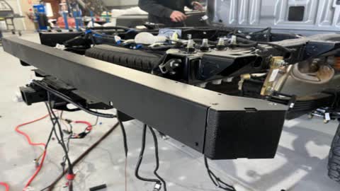
You will have been supplied with the radar mounting kit which looks like this

2
Step 2 of 19

Fit the bar. The bolt should come in from the bottom side.

3
Step 3 of 19

Washer and nut to the top side. Tighten. 18mm socket, 19mm spanner

4
Step 4 of 19

It should now look like this

5
Step 5 of 19
<p>Identify the supplied radar plastics. They should be part number BSB041P.</p>

Identify the supplied radar plastics. They should be part number BSB041P.

6
Step 6 of 19
<p>T30 remove tail lights from Tub. This is to access the Radar units</p>

T30 remove tail lights from Tub. This is to access the Radar units

7
Step 7 of 19
<p>Pull the tail light directly back to pop it out of the tub</p>

Pull the tail light directly back to pop it out of the tub

8
Step 8 of 19
<p>Use a Phillips head screwdriver to remove the radar bracket from the tail light assembly</p>

Use a Phillips head screwdriver to remove the radar bracket from the tail light assembly

9
Step 9 of 19
<p>Unplug radar and remove it from the tail light assembly</p>

Unplug radar and remove it from the tail light assembly

10
Step 10 of 19
<p>Confirm you have been supplied with the correct 3-D printed parts for re-mounting the Radars, this is the part number</p>

Confirm you have been supplied with the correct 3-D printed parts for re-mounting the Radars, this is the part number

11
Step 11 of 19
<p>On the inside, they are marked with passenger or driver to indicate the correct orientation</p>

On the inside, they are marked with passenger or driver to indicate the correct orientation

12
Step 12 of 19
<p>Push the radar into the 3-D printed bracket in this example this is for the drivers side as you can see the word “Drivers” is at the top the right way up</p>

Push the radar into the 3-D printed bracket in this example this is for the drivers side as you can see the word “Drivers” is at the top the right way up

13
Step 13 of 19
<p>Set the 3-D printed retaining clips</p>

Set the 3-D printed retaining clips

14
Step 14 of 19

This is for the driver-side. Push it into the black Radar bracket as shown

15
Step 15 of 19
<p>Identify the supplied screws</p>

Identify the supplied screws

16
Step 16 of 19
<p>Use a Phillips head driver to fit the supplied screws to fix the 3-D printed bracket to the steel radar bracket. There are four screws per side</p>

Use a Phillips head driver to fit the supplied screws to fix the 3-D printed bracket to the steel radar bracket. There are four screws per side

17
Step 17 of 19
<p>Plug-in harness on both sides it is easy to identify the correct plug. It hurt as it has a red tab as shown above.</p>

Plug-in harness on both sides it is easy to identify the correct plug. It hurt as it has a red tab as shown above.

18
Step 18 of 19

Neatly secure all Wiring. job is done

19
Step 19 of 19

Will look like this once fitted