
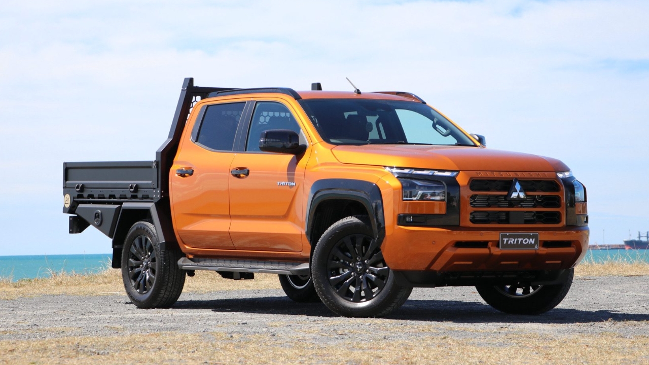
Disconnect battery earth (do not reconnect until all electrics have been reinstated)
Remove the factory tail lights, wiring and brackets.
Remove the factory tail lights, wiring and brackets.
Remove the factory tail lights, wiring and brackets.
Remove the factory tail lights, wiring and brackets.
Remove the bumper.
Remove the wheelie bar.
Lay out tail lights and bumper the same way as it was removed. So when you dissasemble parts they stay on the respective left or right hand sides.
Remove wiring clips and cable ties from light brackets.
Remove wiring clips and cable ties from light brackets. Cut one of the number plate light cables (this will join to the M2 number plate light later) Unplug the other one.
Remove wiring clips and cable ties from light brackets. Cut one of the number plate light cables (this will join to the M2 number plate light later) Unplug the other one.
Unplug camera from harness.
Cut tail light wires as close to light as possible. (The plug and 5 wires will be joined to the M2 tail lights later.)
Cut tail light wires as close to light as possible. (The plug and 5 wires will be joined to the M2 tail lights later.)
Take note of camera orientation before removing.
Remove the camera from the plastic mount.
Re-use the factory small screws and mount camera in the M2 camera mount.
Re-use the factory small screws and mount camera in the M2 camera mount.
Remove screws and plastic clips in bumper.
Remove screws and plastic clips in bumper.
Remove step covers in bumper.
Remove screws and plastic clips in bumper.
Remove all wiring and cable ties in bumper.
Remove plastic bumper skin and remove blind spot monitors. Mark orientation of monitor before removing.
Mark orientation of the reverse sensors before removing.
Mark orientation of monitor before removing.
Remove BSM from plastic housing.
Install BSM in M2 brackets. Ensure correct orientation.
Install BSM in M2 brackets. Ensure correct orientation.
Install BSM in M2 brackets. Ensure correct orientation.
Install reverse sensors in M2 brackets. Ensure correct orientation.
Install reverse sensors in M2 brackets. Ensure correct orientation.
Tighten all bolts once all sheet metal brackets have been re-assembled
Tighten all bolts once all sheet metal brackets have been re-assembled
Note M2 tail lights have a "Top" and an arrow pointing in the direction of the indicator.
Remove roughly 100mm of black outer conduit from the tail light wiring. Strip all tail light wires ready for joining.
Strip all tail light wires ready for joining.

Use this table of wire colours to ensure the M2 tail lights and resistors are correctly joined to the factory plugs and wires that were cut earlier.
Join wires as per table.
Join wires as per table.
Join wires as per table.
Cover joins with split tubing.
Tape split tubing at ends and by resistors.
Strip number plate wires on Triton harness and join 500mm of twin core cable supplied by M2. (Black to black and red to green)
Strip number plate wires on Triton harness and join 500mm of twin core cable supplied by M2. (Black to black and red to green)
Join the other end of twin core to the number plate light in the M2 tray (black to white and brown to red)
Tape over joins.
Cut off the tab with the locating "Tit" on it from the Adblue Breather tank.
Using the templates or measurements cut the large fuel filler rubber hose.
Using the templates or measurements cut the small fuel tank breather rubber hose.
Remove rear fuel tank strap to drop tank enough to access the breather tube on top of tank. (Ridiculous, I know right!) If tank is full, support underneath with jack.
Using the templates or measurements cut the medium fuel tank breather rubber hose.
Using the templates or measurements cut the Adblue breather rubber hoses.
Using the templates or measurements cut the Adblue filler rubber hoses.
Using the templates or measurements cut the Adblue filler rubber hoses.
Assemble Adblue filler and breather hoses as per lay out in video.
Assemble Adblue filler and breather hoses as per lay out in video.
Assemble Adblue filler and breather hoses as per lay out in video.
Assemble Adblue filler and breather hoses as per lay out in video.
Assemble Adblue filler and breather hoses as per lay out in video.
Assemble Adblue filler and breather hoses as per lay out in video.
Assemble Adblue filler and breather hoses as per lay out in video.
Assemble Adblue filler and breather hoses as per lay out in video.
Install fuel filler neck and breather lines.
Install fuel filler neck and breather lines.
Install Adblue tank filler and breather.
Install Adblue tank filler and breather.
Install chassis mounts loosely, note the mounts have cut outs in them FR=front right, FL=front left, C=center and R=rear. The fine thread bolts, spring washers and flat washers go in the front mounts. The M12x35 bolt with flat washers and heavy square washers go in the center mounts. The M12x35 bolt with flat washers go in the rear mounts.
Install chassis mounts loosely, note the mounts have cut outs in them FR=front right, FL=front left, C=center and R=rear. The fine thread bolts, spring washers and flat washers go in the front mounts. The M12x35 bolt with flat washers and heavy square washers go in the center mounts. The M12x35 bolt with flat washers go in the rear mounts.
Install chassis mounts loosely, note the mounts have cut outs in them FR=front right, FL=front left, C=center and R=rear. The fine thread bolts, spring washers and flat washers go in the front mounts. The M12x35 bolt with flat washers and heavy square washers go in the center mounts. The M12x35 bolt with flat washers go in the rear mounts.
Install chassis mounts loosely, note the mounts have cut outs in them FR=front right, FL=front left, C=center and R=rear. The fine thread bolts, spring washers and flat washers go in the front mounts. The M12x35 bolt with flat washers and heavy square washers go in the center mounts. The M12x35 bolt with flat washers go in the rear mounts.
Install chassis mounts loosely, note the mounts have cut outs in them FR=front right, FL=front left, C=center and R=rear. The fine thread bolts, spring washers and flat washers go in the front mounts. The M12x35 bolt with flat washers and heavy square washers go in the center mounts. The M12x35 bolt with flat washers go in the rear mounts.
Install tray system.
Tighten the front mounts in sequence so the mount is sitting evenly on the Triton chassis. This may require you to loosen the top 2 bolts after tightening the base bolt to relax the mount back on the Triton chassis.
Set 30mm-40mm gap between rear of cab and headboard, or headboard water tank. Install M12x35 bolts with flat washer and nylock nut through the chassis mount slots, M2 chassis main runner holes.
Once Chassis is in correct position and aligned to the vehicle correctly tighten all bolts
Tighten the front mounts in sequence so the mount is sitting evenly on the Triton chassis. This may require you to loosen the top 2 bolts after tightening the base bolt to relax the mount back on the Triton chassis. Torque tighten all chassis bolts to 76ftLBs/100nm
Install fuel filler bracket.
Install fuel filler bracket, filler neck and cap retainer.
Install fuel filler bracket, filler neck and cap retainer.
Install fuel filler bracket, filler neck and cap retainer.
Install Adblue breather tank.
Install Adblue breather tank.
Install Adblue breather tank.
Install Adblue filler bracket and filler neck.
Install Adblue filler bracket and filler neck.
Install Adblue filler bracket and filler neck. Secure loose hoses so not to chaffe on any sharp or moving objects
Install Adblue filler bracket and filler neck. Secure loose hoses so not to chaffe on any sharp or moving objects
Install Adblue filler bracket and filler neck. Secure loose hoses so not to chaffe on any sharp or moving objects
Install Adblue filler bracket and filler neck. Secure loose hoses so not to chaffe on any sharp or moving objects
Install Adblue filler bracket and filler neck. Secure loose hoses so not to chaffe on any sharp or moving objects
Install Adblue small breather tube, secure loose hoses so not to chaffe on any sharp or moving objects
Install Adblue small breather tube, secure loose hoses so not to chaffe on any sharp or moving objects
Install wheel guard with M8x25 with sping washers, flat washers and lug nuts, ensure the guard is central over the tyre both front to back, and from side to side.
Install wheel guard with M8x25 with sping washers, flat washers and lug nuts, ensure the guard is central over the tyre both front to back, and from side to side.
Lay out rear tech and lights on the respective sides.
Install tail lights, use anti seize to prevent threads binding. Note: "TOP" and indictator direction arrow.
Install BSM and reverse sensor brackets. Repeat on opposite side.
Install BSM and reverse sensor brackets. Repeat on opposite side.
Install reverse camera bracket.
Install reverse camera bracket.
Connect all plugs from rear tech and tail lights back to vehicle harness.
Connect all plugs from rear tech and tail lights back to vehicle harness.
Rivet the load resistors into the chassis main runners. Tidy wiring and secure with cable ties.
Tidy wiring and secure with cable ties.
Tidy wiring and secure with cable ties.
Tidy wiring and secure with cable ties.
Re-instate battery earth.
Test all tail light functions.
When in reverse, test the reverse sensors and the rear view camera can see the tow ball if vehicle is fitted with one.
Install under tray tool boxes, using M8x25 bolts, flat washers and nylock nuts. Even gap between guard and rear of tray, the door should be flush with the combing rail.
Install under tray tool boxes, using M8x25 bolts, flat washers and nylock nuts. Even gap between guard and rear of tray, the door should be flush with the combing rail.
Install under tray tool boxes, using M8x25 bolts, flat washers and nylock nuts. Even gap between guard and rear of tray, the door should be flush with the combing rail.
Install deck ply, center locate the m6 lug nuts to help with screwing down.
Secure deck ply with M6x30 countersunk decks screws.
Install sides and tail gate.