
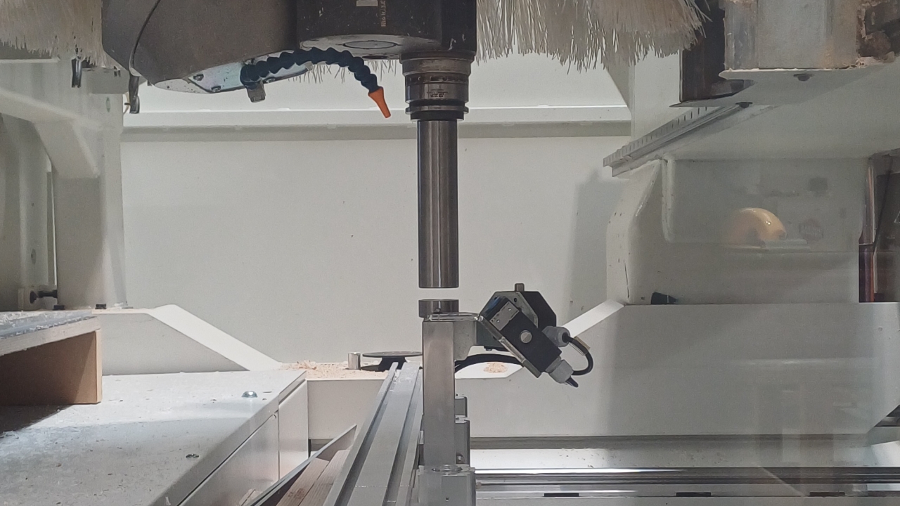

Bolt the kinematics kit onto the fixing plate.
Ensure the contact surfaces are clean from dust and grease

Connect the communication line with the sensor.
The cable is usually tucked under the machine

Ensure the clocking bar is clean, especially the spindle contact surfaces

Take a tool out of the linear rack and put the clocking bar in its place.
Take note of the tool number of the original tool that was in the tool rack!

Clocking bar in the linear rack

Load the clocking bar into the spindle, by instructing it to load the original tool number.
The clocking bar does not have it's own tool number, which is why we do this step.

In PanelMac go to MDI>ISO, enter "G141"
Enter
Press the start cycle on the handheld control
The calibration cycle will now begin. You will get a series of messages and will be instructed to press cycle start regularly.
Pay attention to what is displaying on screen in PanelMac

The first check is to check the sensors are working.
Check the vertical sensor by depressing it, if it is working, it will ask you to press cycle start to proceed.

Check the horizontal sensor
If there is an issue with the sensors not communicating with the machine. Do not try to proceed with the cycle.
Contact SCM support or their reseller.

Ther first check will be over the round disc.
This is a visual check to see if the bar looks centered over the disc.
If it does not look aligned, then stop the cycle. It will need to be mechanically adjusted to within a certain tolerance before this cycle will work.

The C-axis will rotate by 90deg, pay attention to how centered the calibration bar is over the disc.
Sometimes you might see the movement of the bar as it rotates, which would highlight the misalignment.
If everything is perfect, it should look like the calibration bar does not move at all, as the spindle rotates about c-axis.
Same comments as previous step apply.
The CNC will go through a series of checks to check the B & C axis.
When prompted, press the start cycle button to continue to the next check.
The cycle can compensate for a small amount of error. If it does detect some error, it may loop through the same check multiple times. Each time adjusting the B or C axis rotation to zero in on the correct alignment. If this happens, follow these steps.
If the alignment of the spindle is beyond this error tolerance it will only be able to go so far in the cycle before it will display a message saying the B or C axis is not ok. If this happens, the spindle will need to be manually shimmed to correct it to within the error tolerance allowed for this cycle.
The cycle cannot be continued if you get this error.

If there are no faults detected with the spindle orientation, the cycle will finish
Run the command through MDI to unload the tool.
Remove the clocking back from the toolholder and replace it with the original tool! This step is very important.

Unbolt the sensor plate and carefully pack everything up again.